Welcome to the ATW800/2 page – read that as you like: “ATW800 two” or “ATW800 half”, depending on your expectation.😉
Whatever way, it’s the Atari Transputer card as it was meant to be.

Quick navigation
If you (re)visited and looking for something specific, here’s the fast lane:
- Background
- Features
- Technical background
- FAQ (separate page)
- Wiki (in the works)
- Software (Nextcloud share – Drivers, Docs, Tools, Helios etc…)
- Reserve or buy one?
| 📰📢 Newsflash: The ATW800/2 made it into HACKADAY! 🥳
And we got our first unboxing video! Thanks for that TJ! Here’s another “happy TJ” 😉 |
Background
Before we go into features & technical details I’d like to talk a bit about motivation and goals of this project.
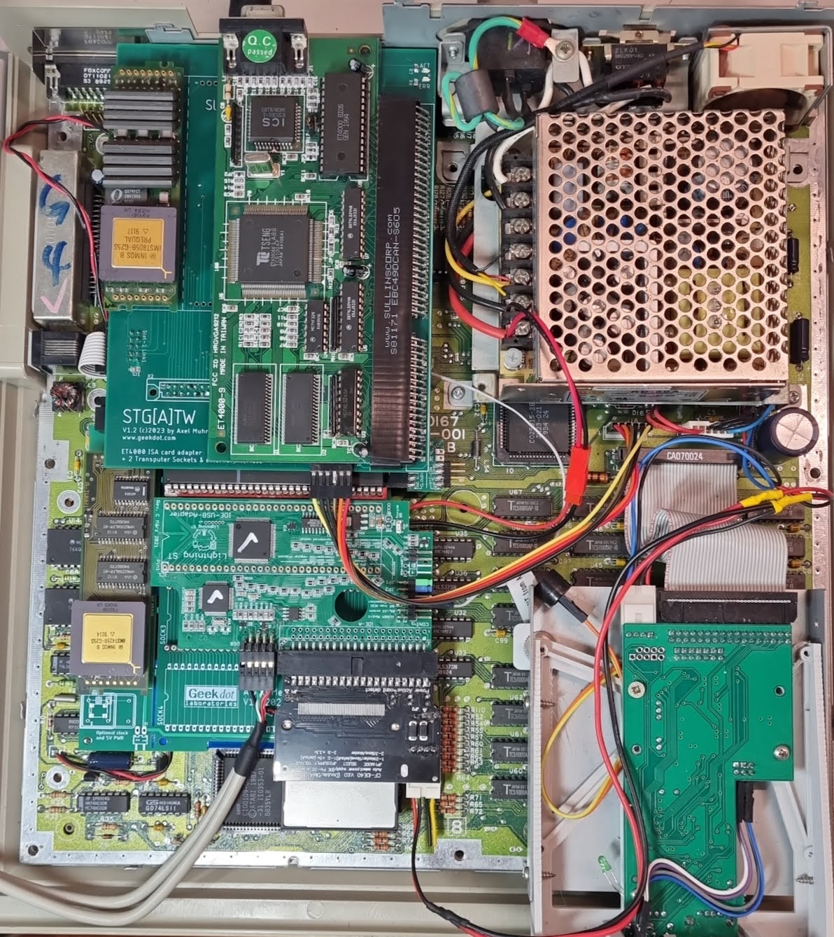
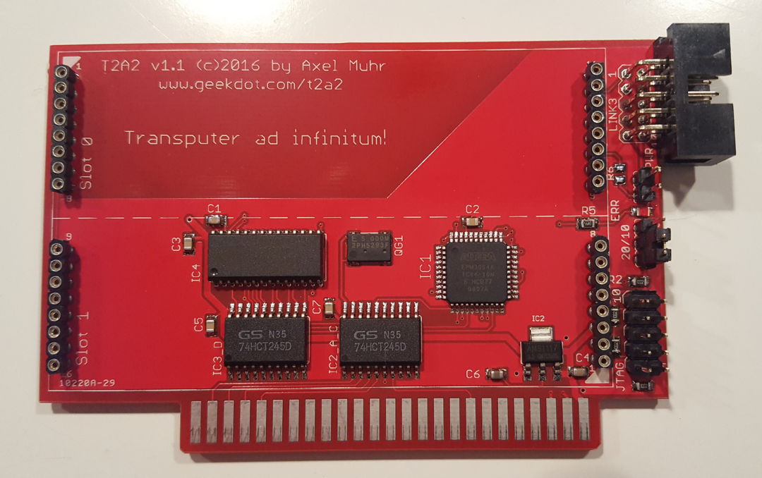
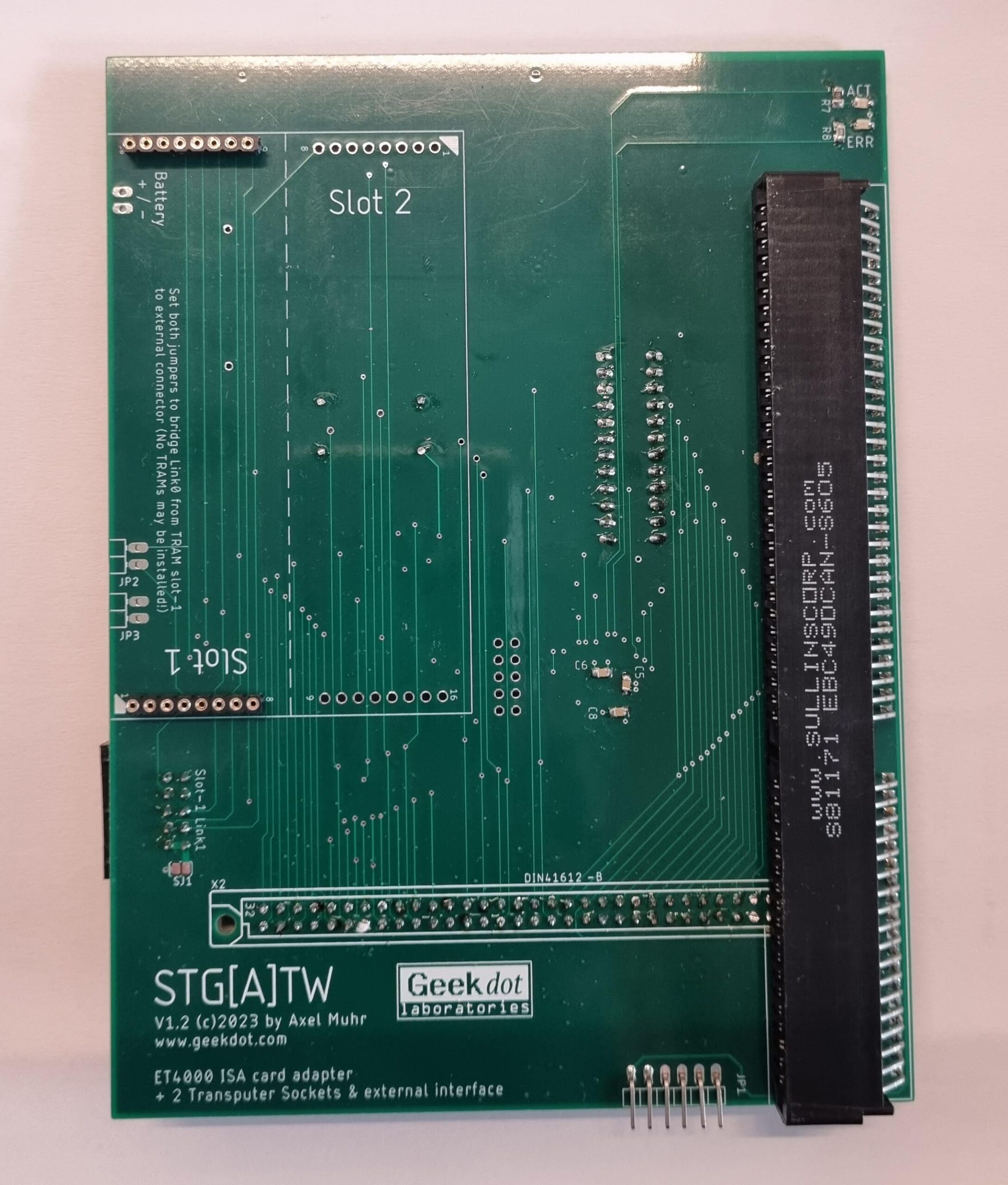
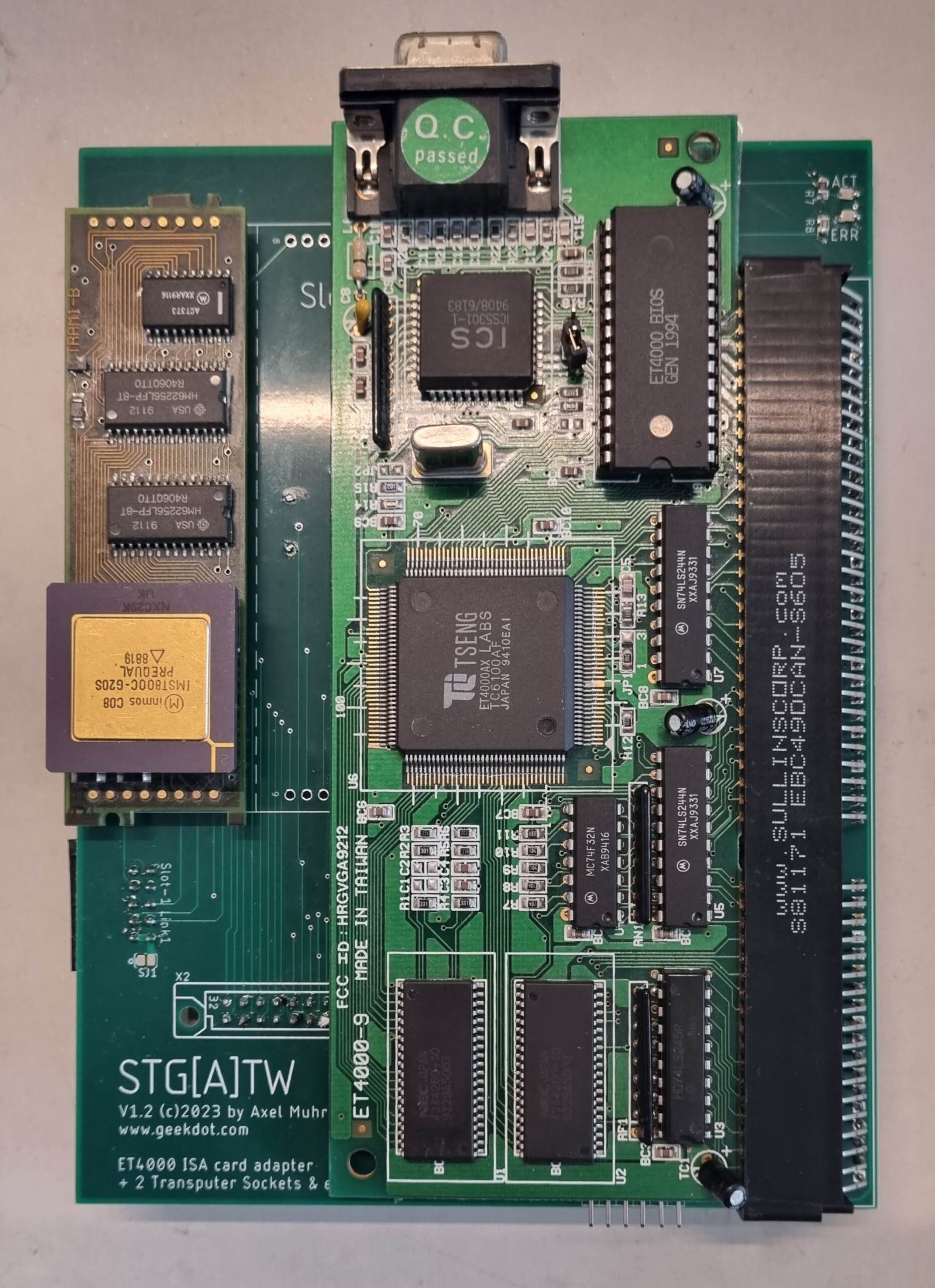
You might have read about my STG[A]TW card for the ATARI Mega-ST expansion bus. That contained an ET4000 graphics card borrowed from IBM PC ISA-land and an Inmos C011 Link-Adapter to connect to a Transputer CPU.
This showed the direction but was a bit cumbersome. Also, ET4000 cards are getting hard to find, expensive (>100€) and not all of them actually do work in your ATARI – and most important, my intention was to create something affordable – remember: Power without the price ✊
The idea is/was to provide a plug-and-play version of a expansion which brings your ATARI as close as possible to what the ATARI Transputer Workstation (ATW800) provided.
That is: Transputers of course as well as expanded graphics capabilities.
Here are my 6 goals I want(ed) to achieve:
- Be reasonably ‘historically correct’
- Create a design avoiding obsolete parts where possible
- Stay in a affordable price range
- Simple installation
- Integrate/play nice with other peripherals
- Offer flexibility
Goal #1 is a philosophical topic one can discuss for his/her whole retro-nerd life. It’s the same as with e.g. cars. Is it OK to put an US V8 into a Ferrari? Electrifying a 1970 Porsche 911? LED headlights in a vintage car? Trailer Queen or patina? The list and discussion will go to the end of humankind.
The very same goes for vintage computer systems. There’s nearly none left which hasn’t had a Raspberry Pi of some sort slapped into it. Starting with a Pi Nano as WiFi-module and ending with a full blown 1.5GHz Pi 4 in an 8bit machine… for my taste, this is not the way.
So with this project we stay with what would have been possible in the let’s say 90s. It might be reached by using more integrated parts, but no recent high-tech here. Sorry. Which brings us to the next point…
Goal #2 is more or less a financial decision. If you use parts which are long time out of production, you depend on a grey market which is limited and can quickly drain, might be full of fakes and prices explode due to greediness.
So instead of buying the last stock of e.g. ET4000W32 chips and create a redesign of an x86 ISA card kludged onto a 68k bus, it’s wiser to go for a ‘virtual design’ which won’t go EOL and can grow as we go… in this case: FPGA is the way. But following goal #1, don’t overdo.
If there’s (currently) no other option, we obviously have to go with the old parts. The Inmos C011 link-adapter is an example here.
Goal #3 limits #2 in some aspects. It’s relatively simple to pick a recent FPGA which actually would be capable to easily simulate your whole ATARI ST (or two)… but that would be quite expensive – not just the chip but also the design, which requires external RAM, 3-4 voltages and multi-layer PCBs to cope with 200+ BGA connects.
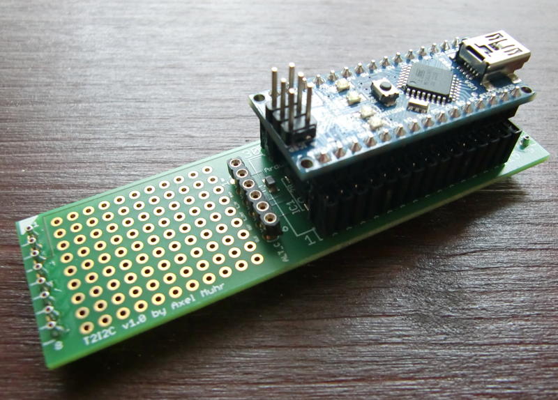
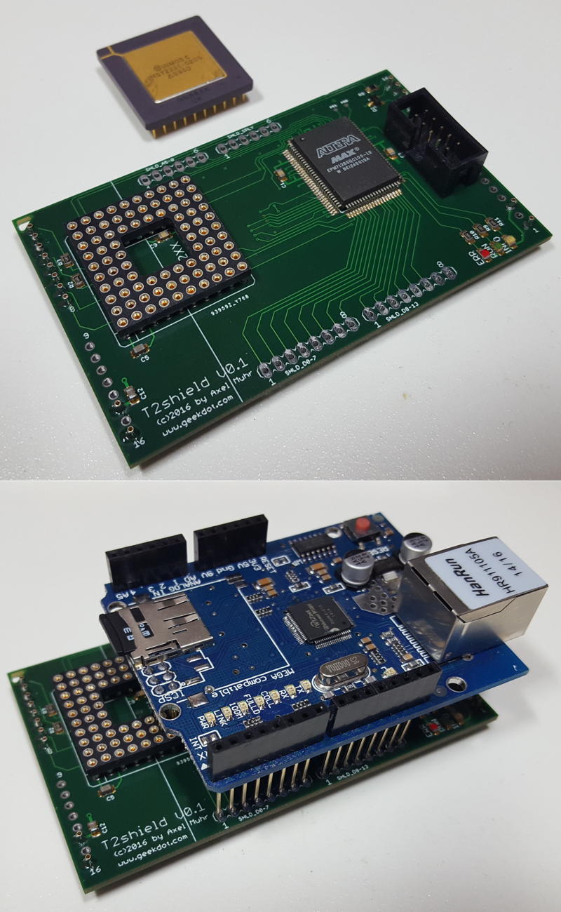
The compromise here is an FPGA board which offers all that already mounted onto it and will be piggy-backed onto our card.
And because cheap is always a challenge, we went for the Chinese Nano FPGA family which has an unreached price/feature ratio and fits the “Power without the price” mantra.
Goal #4 is quite simple: Not everybody is a virtuoso with his/her solder iron. So I tried to avoid as much additional soldering/cabling as possible.
Basically you plug the card into the Mega-ST or VME slot and you’re good to go.
In fact, as of today, there’s just one cable to plug(!) if you want to use one optional feature of the ATW800/2 (ACSI INT). No soldering whatsoever.
Also, you should be able to plug the card in and use it without additional needs. That’s why it offers (optional) TOS ROMs.
This is the way 😉
Goal #5 reflects the awareness that there are mostly souped-up machines out there. I daresay no one who plays with uses his Atari unenhanced in one or the other way.
The ATW800/2 tries to play nice with other common expansions by precisely decoding (previously unused) addresses and even integrate their features like the looped-through USB port of the Lightning-ST.
That said, there are so many old and new peripherals that nobody can guarantee that everything works nicely together with an ATW800/2 – especially on an overloaded bus.
And because of this Goal #6 will be covered by “bespoke ordering“.
Not everybody will be interested in having 2 TRAM slots for hosting real Transputers – so you can leave them out and save some €€.
The same goes for the TOS ROMs. If you already have another ROM switcher, just leave it unpopulated.
Reality kicked in
Having all that planned out, back to the drawing board I went… just to realize that I cannot handle that all by my self.
So it became clear that I have to ask specialists if they like to join the effort.
Let me introduce you to the team aka “The league of extraordinary Transputer gentlemen“:
- Wolfgang ‘Idek’ Hiestand of the Nova drivers fame.
Back around the start of the 2000s, Wolfgang looked into getting his hands on the Nova source code with the intention of preserving knowledge about Nova cards. It took some time, but in the end he succeeded in recreating the original drivers. Since then, he has maintained and extended Nova drivers to support additional VGA cards and ATARI computers. For this project, Wolfgang has created a branch of the Nova drivers to support the FPGA-based card. - Claus Meder. God of all things FPGA and fellow Transputer maniac. So much actually that he wrote a Transputer core in VHDL.
Claus designed and wrote the impressive graphics-core for an FPGA from hell. - André Saischowa. Atari and Transputer fiddler of the earliest hours. He wrote Transputer and Atari ST programs back then and just got into the matters again when we met. Perfect timing!
André ported all INMOS tools as well as the Helios server… plus developing driver .sys files for NVDI. - Honorable mention: Mike Brüstle of transputer.net. The man whose brain natively runs Transputer assembly code.
When you have a question regarding Transputers and he doesn’t know the answer, nobody does.
All four of them have many, many more talents and without them this project would still be just another dream of mine. ❤
Features
Ah, finally… features.
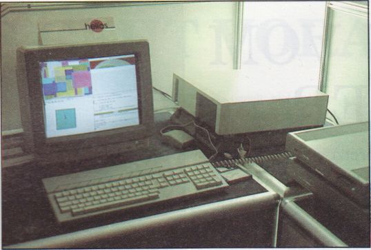
I assume you’re roughly in the picture, what the ATARI Transputer Workstation was all about. Basically, it was a Transputer system running Helios which used an Mega-ST1 as host. The powerful graphics chip (“Blossom“) was connected to the Transputer which ran X11 on it to display graphics in 1280 by 960 pixels (16 colors) or 1024 by 786 pixels in 256 colors, making the most out of its 1MB VRAM.
As said the Atari part was mainly just I/O: Harddisk, keyboard, mouse, serial and parallel interface. No access to Blossom and after booting, there was no way to run Atari software from/in Helios.
Today that’s bugging me, and like said before, I think Atari or Perihelion, the company behind Helios as well as the ATW, took the wrong approach.
The Transputer system should not sit on top of the Atari system but next to it. Both, TOS/GEM as well as the Transputer(s) should have access to all that pixel beauty.
So there you have it, the two main features and ‘raison d’Être’:
High-Res color graphics 👾
The ATW800/2 graphics controller is actually a tiny and cheap FPGA board piggybacked onto the card. While we started out with the Tang Nano9k it soon proved to be unstable as soon you stretched it to the max… as for now, we changed to the slightly more expensive Nano20k which therefore offers more room and faster/bigger RAM.
[NB: This is the prefect proof that it does make sense to keep this part “virtual” – no shortcoming or chip EOL’ing can stop the product itself. All it needs is an adaptor.]
Displays will be directly connected to its HDMI port.
The running core, called “Seurat” (named after the inventor of Pointillism), has access to 2MB of VRAM, which is twice what Blossom had. Thus there are quite some resolutions possible (in 2, 8 and 16 bit colors):
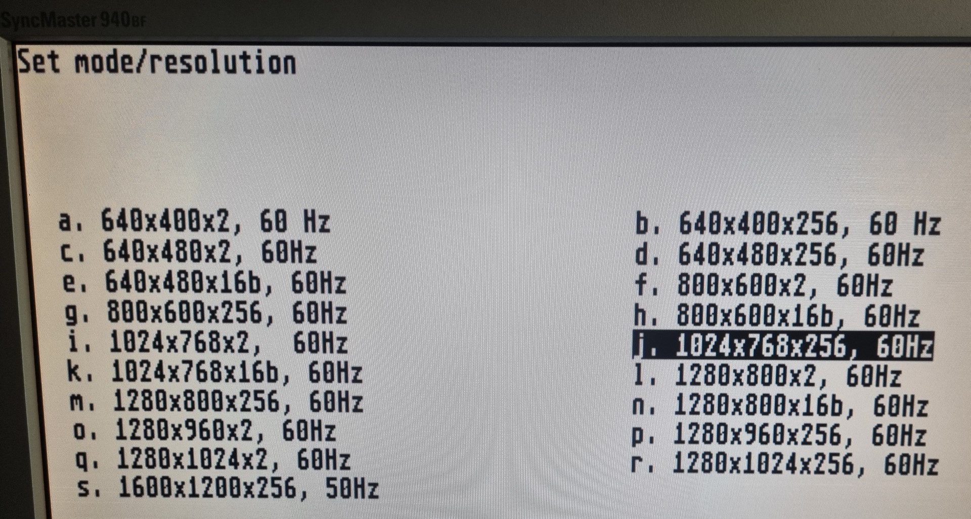
Woo-hoo… holy Bat-Resolution! 🤯 (1600×1200@256)

To cope with such an amount of pixels Seurat features a blitter with is able to push roughly 130MB/s for fast redraws and smooth scrolling.
As of today (July 2024) the current Gembench 6 numbers vs. 640×200 ST-Med (no NVDI!):
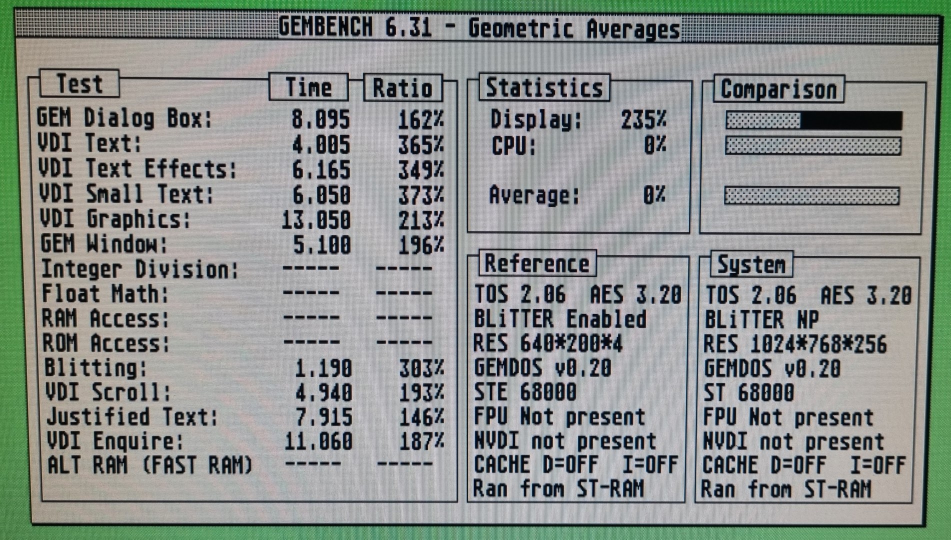
Transputer(s)
Yes, they might not be of everybody’s interest, but they were the main actor in the ATW800 and are fascinating beasts when you take a closer look at them.
32bit RISC’ish CPUs, running at 20-30MHz, each having 4 links to directly connect to other Transputers. That way one can create a massive, unlimited parallel system that blew away anything you could run at home back in 1990.
This strictly follows my goal #1: Historically correct. Run things on the real stuff and feel how an ATW800 felt back then.
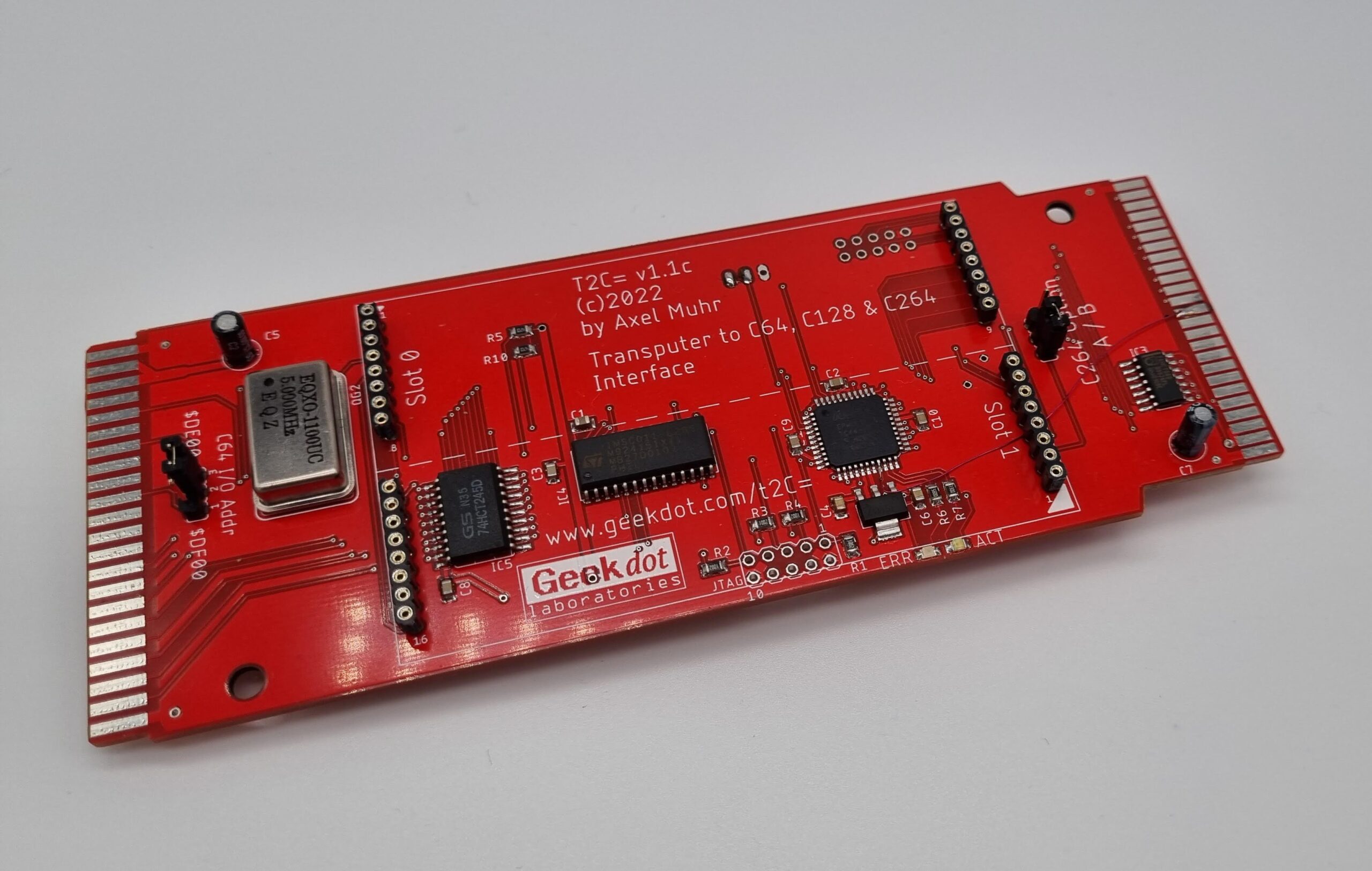
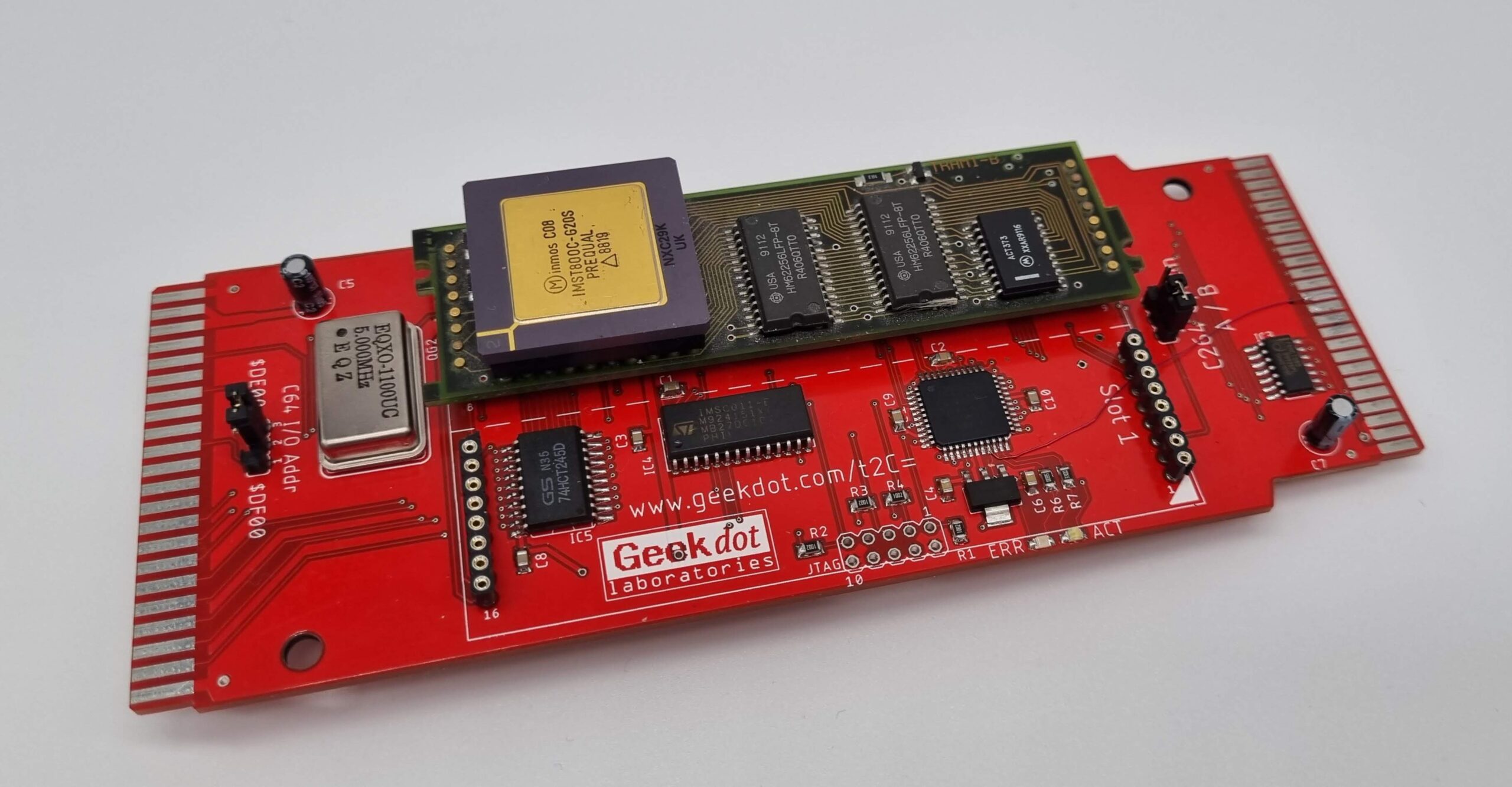
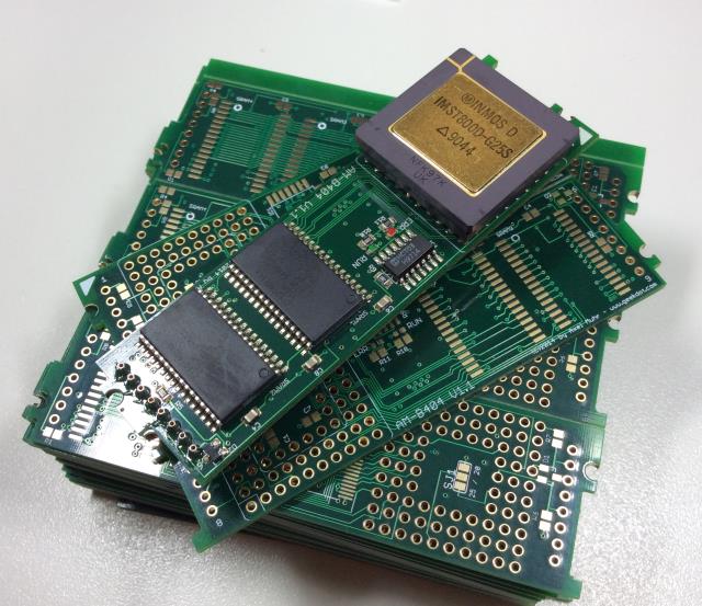
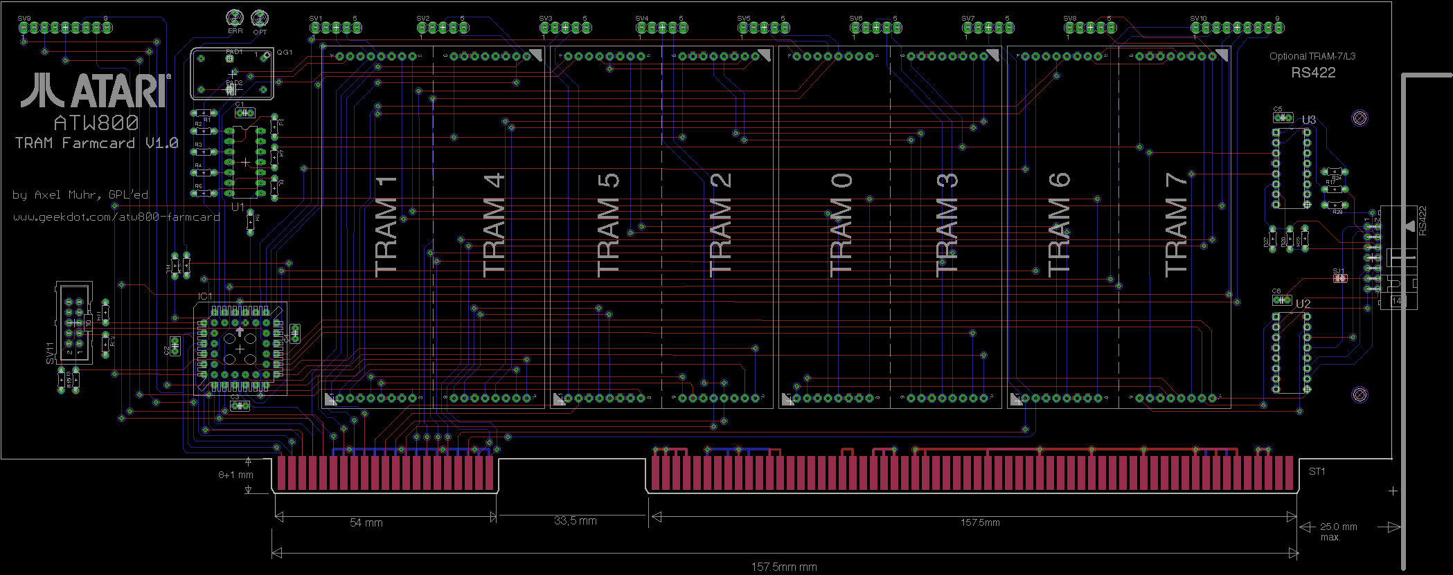
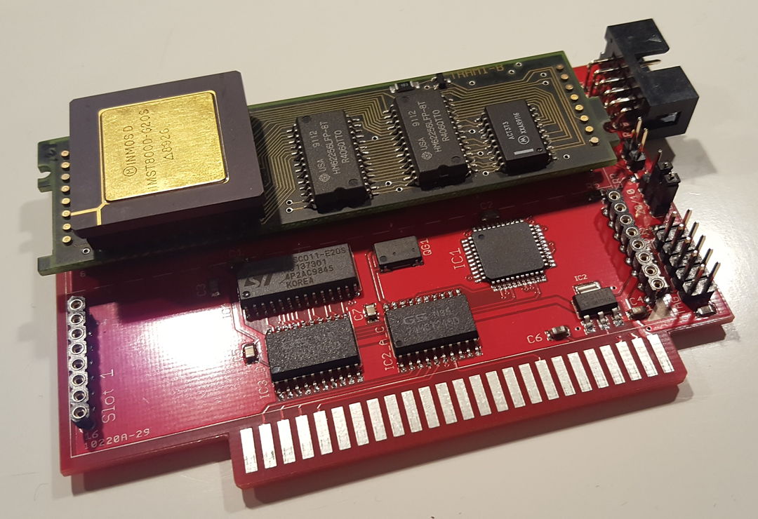
The ATW800/2 features 2 slots for classic size-1 TRAM modules next to the Nano20k. Here’s one size-1 TRAM installed:
TRAMs were/are available in many configurations, for those who want to know more, I made a dedicated page about TRAMs.
But that’s not all. Because Claus isn’t Claus without some sort of magic, he also added a synthetic Transputer core into Seurat.
That core is 100% T425 compatible and can not only access his own RAM (6MB, can be partitioned by the user) but also the Video-RAM… like Blossom did.
To make everything perfect, this synthetic Transputer has a link to the physical Transputers on the ATW800/2 which are also linked and themselves have a link at the edge of the card to connect to the outside world.
To round this up:
Everything is shared with the Atari host. You have access to the physical Transputer(s) and the synthetic ones over the 68k bus.
GEM has access to the VRAM as do the synthetic Transputers… and indirectly over their links, the physical Transputers, too.
Given proper programming, the possibilities are endless. Here are some ideas:
- Accelerate Atari programs using Transputers (send data, let them do the math, collect results)
- Run X windows on Helios (running the X client on a synthetic Transputer).
- Use the synthetic Transputers as GPU. Let them do the VRAM manipulation. Lines, vertices, transformation… you name it.
Additional features (for the Mega-ST)
But wait, there’s more 🤓…
Like I told you in the beginning, I’d like to be this as much plug-and-play as possible. So the ATW800/2 features 1MB in-system programmable Flash ROM. That ROM can host 4 different versions of TOS selectable by two DIP-switches at the back-edge of the card.
Next to that DIP-switch you’ll find a dual USB port. That is a dumb loop-through to the front left edge of the ATW800/2. It is meant to connect an optional Lightning-ST so you have a nice & clean way to lead those connectors to the outside without cutting holes into your Mega-ST case.
Alternatively you can use these port to power external ACSI drives like the ACSI2SD or ACSI2STM etc.
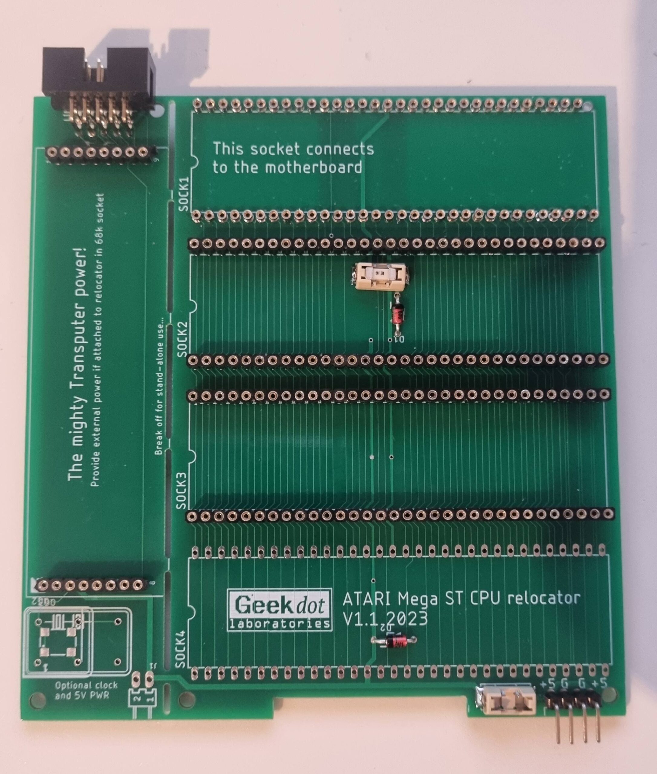
Besides the 3 external Transputer-Links there’s also an internal one at the cards front. Just in case you have my relocator installed…
The ATW800/2 features a battery-holder for a coin battery. Because the original AA battery compartment of the Mega-ST can get in the way with the ATW800/2, this might have to be cut out 😥.
That holder can then replace the original one.
And finally, because the Nano20k has it already on-board, we’re to providing a harddisk interface using the Nano’s Micro-SD feature.
This feature is seen as a free add-on, not a real feature as it is a bit picky about the Micro-SD card used – thus we still consider this feature being at ALPHA stage.
We strongly recommend known brands like SANDISK. No-names will give various results from working up to desaster.
Why “Mega-ST” only?
Well the ATW800/2 is also available for the VME bus, i.e. Mega-STe and Atari TT.
Most of those optional features aren’t needed in those systems. Also VME cards require a 0.5mm unpopulated edge on both sides to slide into its cage.
- ROMs cannot fully served through the VME bus.
- When installed in the VME cage, there’s nearly no way to feed in the USB connector of a Lightning-TT.
- Same goes for internal TRAMs and a battery cable.

There you have it. This is all we’re able to talk about right now. Some smaller details might change until the release – that’s called ‘agile’ 😏
Let’s sum it up again:
The ATW800/2 will be available for the Mega-ST bus as well as VME bus. This is our progress so far. It will be updated every time we think it’s worth doing so.
Technical details
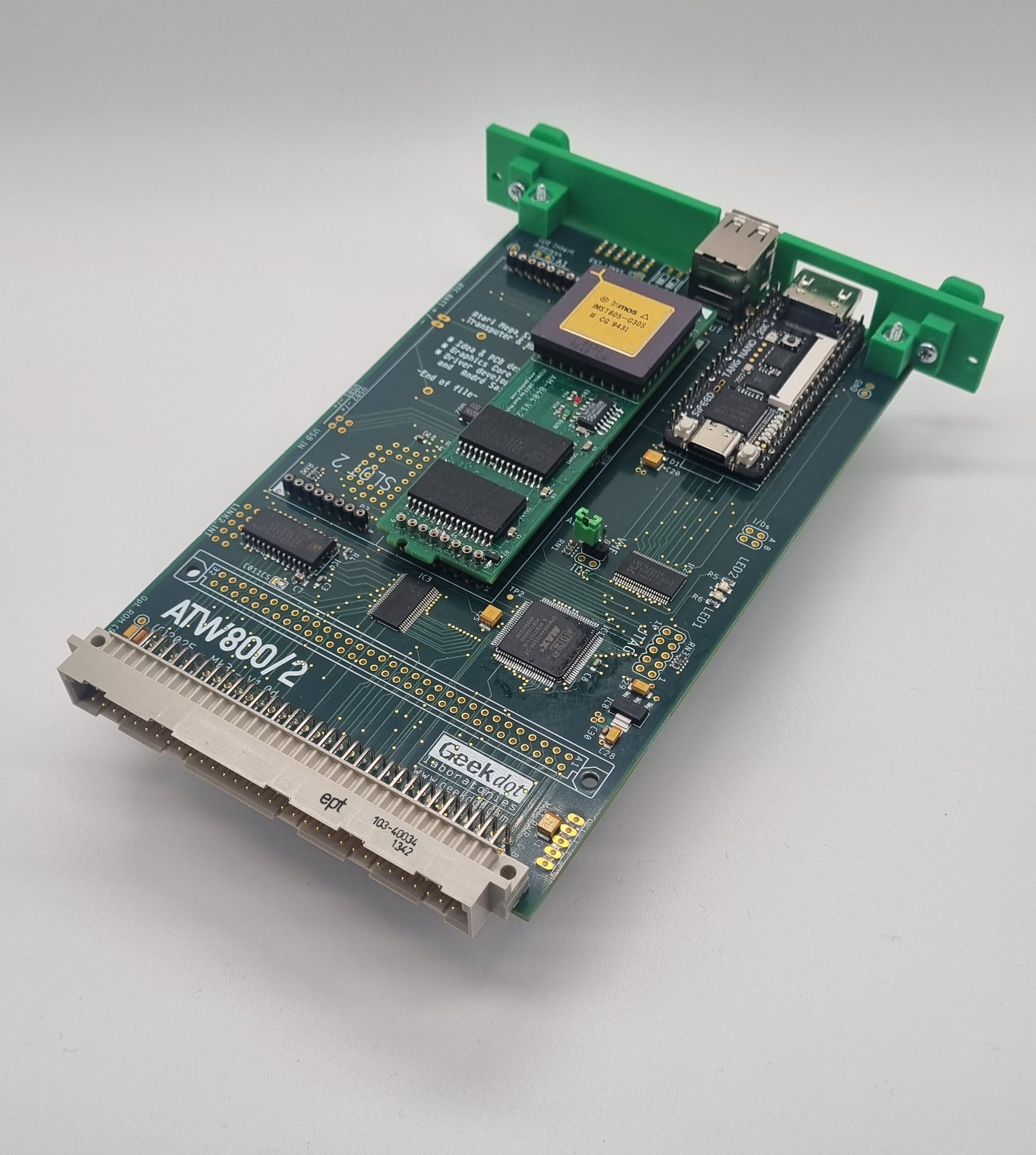
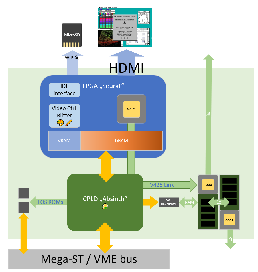
The ATW800/2 basically consists of 3 main devices:
- The FPGA (“Seurat”)
- The CPLD (“Absinth”)
- The Inmos C011 link-adapter
Absinth is the glue to the system-bus. He decodes addresses, manages the different functions on the card and controls the C011. He’s also the gateway between the 5V and 3.3V worlds.
Seurat itself, the core within the FPGA, consist of the Framebuffer controller, a blitter and (currently) two one synthetic T425 Transputer cores. The 2nd core was scarified for more Transputer Memory or VRAM.
This is a schematic representation:
| This was the pre-announcement in July/August 2024
And for those, who haven’t watched it… here’s the hastly made YT video 😅
…and another one showing the card running on the VME bus of an ATARI TT |
Ok, ok shut up and take my money! 💸
Great, you got hooked! 😉 In this case, here’s a dedicated post on how to get one.
I’m building them in batches of 50 pieces. So it’s either an open list for an ongoing batch you can get added to or, if the list is already full, a “subs’ bench” where you can sit and wait if one of the players on the field needs to be replaced…

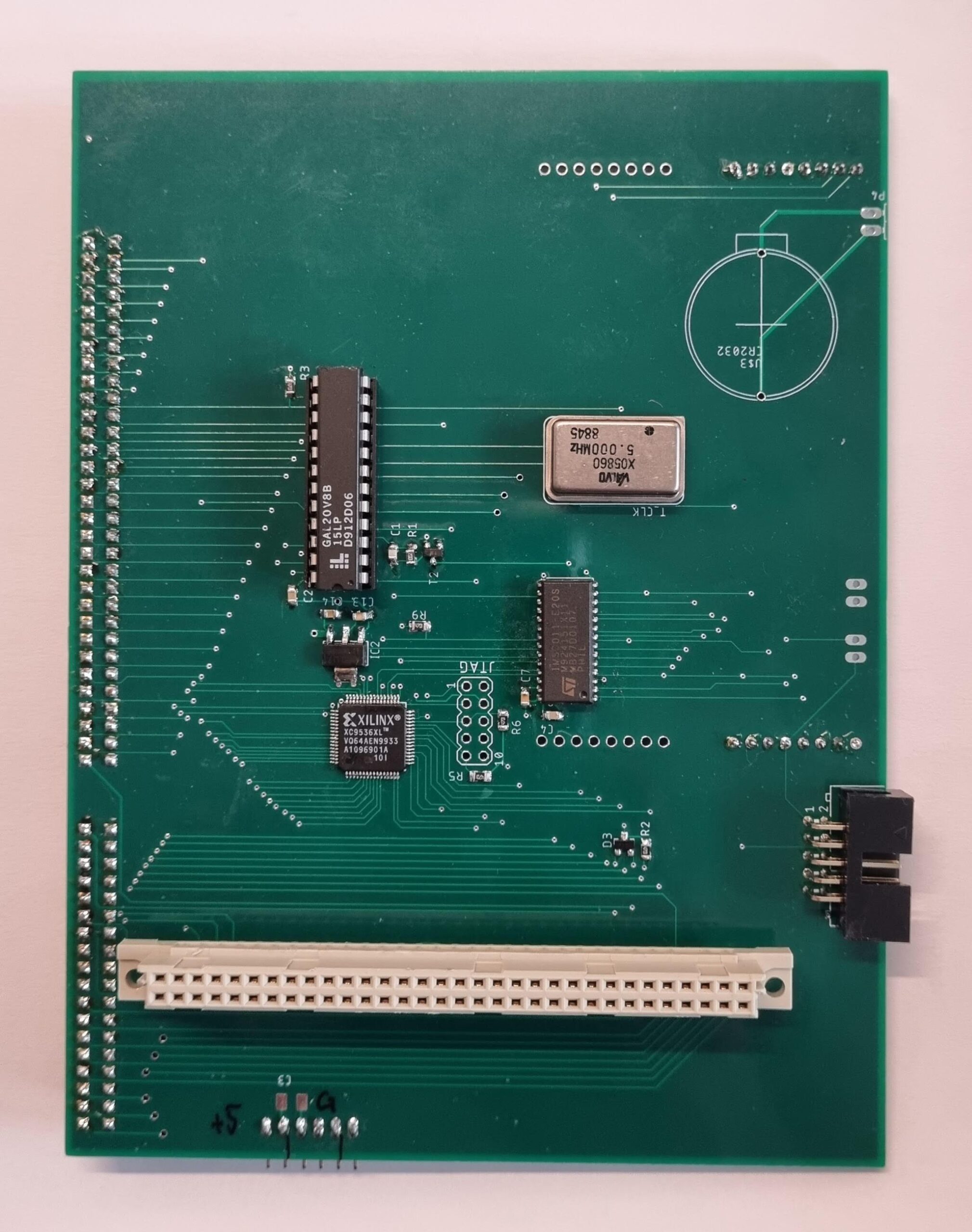
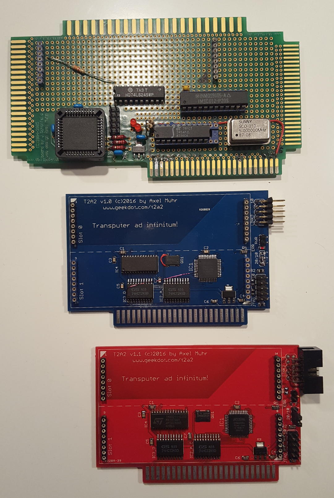
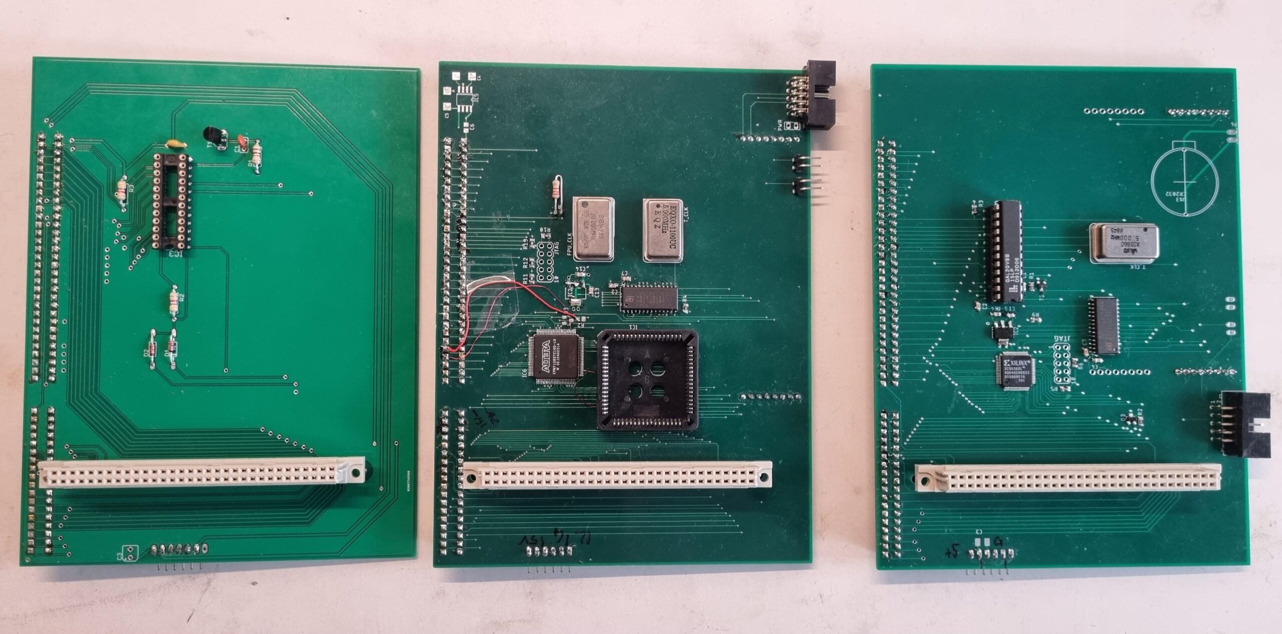 From left to right: STGA, the Über-STGA and the final STG[A]TW
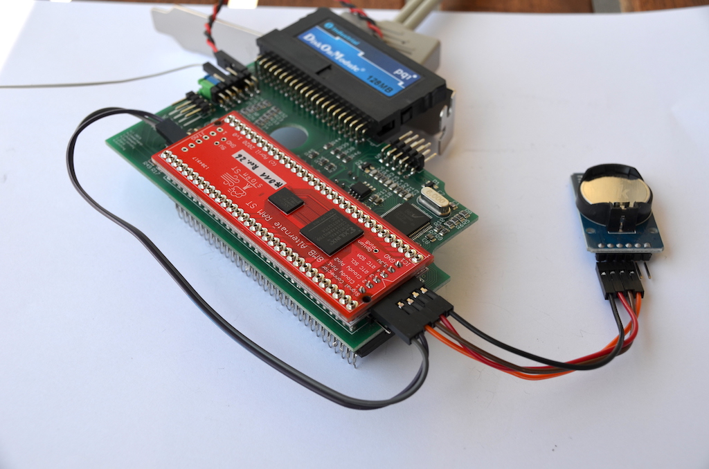 This can get tricky in some crowded Mega ST cases…