
Boy, my acronyms are really getting Star Wars’ish now… After the T2C64 and the T2A2, T2I2C sounds like a new protocol-robot but stands for “Transputer to I2C (Bus)”.
The I2C bus is a comparably slow serial bus – even to the Transputers 1990 standards – but in contrast to the Transputer OS-link interface I2C is still alive and kicking… even more since those simple-to-tinker-with controllers like ATMEGA or PIC made there way beneath your soldering gun.
As you might have guessed by now, the I2C bus wasn’t my primary intention to do this interface.
Since I started fooling around with Transputers I was thinking of an LED “CPU load display” like the one the lovely BeBox had… just bigger, a real manly Blinkenlights 😀 It should be at least capable of showing the load of up to 32 Transputers…
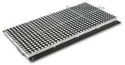
So I stumbled across a very nice bi-color 32×16 LED panel (Sure Electronics DP14211 – it seems in 2022 that company was either sold or folded), which is quite easily controllable through one small ATMEGA controller.
By incident, a friend of mine gave me an surplus Arduino as a present and the decision was made. I’ve build & programmed ATMEL devices before, but Arduino plus breadboard can’t be beaten if you need to get something done quick.
Blinkenlights
It’s quite straightforward to connect the panel (can one say “display”? Nahh.) to the Arduino. To make things even more ‘bus-y’ the ATMEGA talks over just 4 wires to the panel over SPI bus – yet another serial bus, but luckily we don’t have to care about that fact as there’s a library handling this.
So after some days of coding, the “panel firmware” was done. The Arduino is happily talking to the panel over the SPI bus and listening on his I2C bus (another 4 wires) for commands and sends the calculated output to the panel.
Commands? Well, I was thinking about how to handle the data in an efficient manner. The most simple way would have been to have the Transputer sending the complete 32×16 ‘bitmap’. For a bi-color panel (2 bits per pixel) that would have been 1024bits/128bytes each time/interval.
To be more flexible I came up with a 3-byte command structure – for details see the next post.
Old guy speaking new language
So how to connect a Transputer to an IC2 ‘device’? We need two things for that:
- The good ol’ C012/11 Link Adapter – turning Transputer links into an 8-bit parallel bus
- An 8bit bus-to-I2C converter
We saw the C012/11 in some of my projects already, so piece of cake here. The 2nd converter needed some research and was easily found: A Philips/NXP PCF8574(A). So without control-lines the setup is quite simple:
Transputer → C012 → PCF8574 → Arduino → LED panel
After some hassle with handshaking (see next post “nitty gritty details”) I was able to send bytes to the display using MS-DOS’debug.exe to write bytes to the standard Transputer link IO ports (0x150++, you should know that by now ;-)) using a nice tool called ‘iskip.btl‘ from the INMOS ANSI-C Toolset (also available in my Transputer Toolkit). It simply shortcuts one Transputer link to another, e.g. Link 0 to Link 2. This relieves you from removing your Transputer and put jumper-wires into its socket… very nice and clean solution.
Doing it the right way
Well, while talking to devices through debug is definitely geeky, it’s not what I wanted as a result.
Having more than one Transputer running, watching its CPU and probably RAM load leads to the inevitable target of Helios. At least that’s the No.1 reason I created this interface… but with the command structure of the ‘firmware’ you’re obviously not bound to that OS, e.g. OCCAM programs could control the panel, too.
So the biggest development part was creating a clean way of taking to the panel while running Helios. For debugging and testing I wrote a simple command-line tool which opens a link on the Transputer you have the shell running on, then it sends what ever byte you added as parameter. Fine.
Next was version 2 of that tool, sending 32 fictional CPU-load values (0-100%), version 3 did the same adding RAM-load values.
Then it was time to do it the right way – so I dived into the sources of ‘network‘. network is the Helios tool for examining the Transputer (not IP!) network(s), so it shows the actual load in nice bar charts etc. – pretty much like top does on todays Unices.
While the sources of Helios are available, they seemed to be accumulated from different sources, dumped into an ISO image without caring for symbolic links etc. – in a sentence: They’re a mess.
After some days of try’n’error I was able to compile the sources of network. This made network2 (working name) possible which includes the new parameter ‘led’ followed by the number of the Transputer link to be used, eg. ‘network2 led 2‘ results in displaying the current CPU/RAM load of all Transputers in the network on the panels.
CPU-load is displayed by red LEDs, RAM-load uses green LEDs, overlapping is shown orange. As long as there are up to 32 Transputers each line represents one Transputer (using 16 LEDs). If there are >32 and <65 each line will be split into 2 columns (8 LEDs for each Transputer). This goes on for >64 and <97 (3 columns) and finally 4 columns for up to 128 Transputers – this isn’t very ‘readable’ anymore given there are only 4 LEDs left for one Transputer, but hey! It’s Blinkenlights, who cares!?
So without much further ado, here’s the prototype-beast in action:
For more details, thoughts, outlook and code see the next post.