Tag Archives: demo

Putting the DSM to use

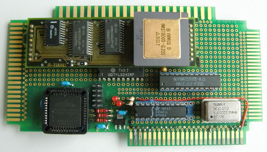
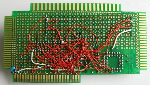
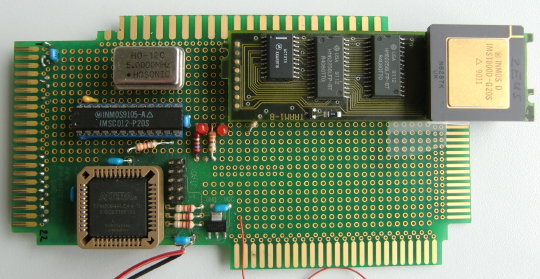
So after the lengthy description of the DSM cards – how can we make use of them? As said in the previous chapter, they were shipped with an assembler and even an early version of GCC (1.3) so development is pretty straightforward.

Activation

First, you have to understand how the cards integrate themselves into an ISA/EISA system. While the three versions (8, 16, 32bit) differ in some areas, the integration is more or less similar:

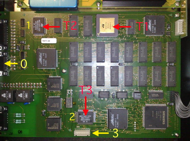
Each version offers a latch for controlling the card. This means to activate the card by writing bits to that latch to define a memory-window inside the hosts RAM to blend-in the cards dual-ported RAM  and/or resetting it etc.. The latch is accessible through an IO-port set by jumpers on the card (default 0x300).

So for the ISA cards you have to for example write a 0xC2 at that port-adress to reset & activate the card and use the mem-window of 0xDC000-DC7FF. In Turbo-Pascal this would be something like:

port[$300] := $c2;

This gives you a 2K mem-window to exchange data between the DSM and the host (just 1K for the DSM860-8).

The EISA cards obviously use other ports depending on the slot-number, so this would be an example to do the same for am DSM860-32, this time in Turbo-C:

outportb(slot_no * 0x1000 + 0x800, 0xc2); // For slot #2 this would be 0x2800

This would also open a mem-window at 0xDC000, this time up to 0xDCFFF, i.e. 4K long.

Memory

As mentioned above, the Host and the DSM-card are communicating through a memory-window of diffenrent sizes, depending on the DSM used. Due to their nature, the memory is looking different though. That said, at least they’re both litte-endian, so no byte-swapping needed.

The 80×86 side

For the hosting PC, memory looks pretty straightforward. 1KB-4KB of RAM somewhere in ‘lower-RAM’, that’s it.
While we don’t use it, it’s worth mentioning that there’s a 2nd memory window called “Common“. This is fixed at a specific address and is shared between all possible cards plugged into one host. I guess you already got it: This enables easy multi-processor communication… and gives a lot of possibilities for f**k-ups.

The i860 side

The memory-mapping on the i860-side is the same for the 16 and 32bit cards, the dual-ported RAM is located at 0xd0040000 (0xC0000000 for the DSM-8).
In any case the i860 memory is linear, 64bit wide and always on a 64-bit boundary. This means you have to read the DP-RAM area differently depending on which card you run your code. Here’s an example of how the DP-RAM looks like on the Host- and i860 side:

Host DP-RAM in DOS ‘debug’
-d dc00:0000
DC00:0000 11 22 33 44 55 66 77 88 ...

which would look like this on the i860 side:

DSM/8
C0000000 - 11 xx xx xx xx xx xx xx 22 xx xx xx xx xx xx xx
C0000010 - 33 xx xx xx xx xx xx xx 44 xx xx xx xx xx xx xx
C0000020 - 55 xx xx xx xx xx xx xx 66 xx xx xx xx xx xx xx
C0000030 - 77 xx xx xx xx xx xx xx 88 xx xx xx xx xx xx xx

DSM/16
D0040000 - 11 22 xx xx xx xx xx xx 33 44 xx xx xx xx xx xx
D0040010 - 55 66 xx xx xx xx xx xx 77 88 xx xx xx xx xx xx

DSM/32
D0040000 - 11 22 33 44 xx xx xx xx 55 66 77 88 xx xx xx xx

So reading and writing from/to the DP-RAM involves some thinking to be done by the programmer. Here are two code-snippets showing the difference between reading the DP-RAM on a DSM860-8 and an DSM860-16. First the ‘8 bit version’:

mov 4*8,r4
readloop:
ld.b 0(r15),r14  // Load BYTE from DP-RAM
st.b r14,0(r29)  // store it destination
addu 8,r15,r15   // add 8 to read-mem-pointer
addu 1,r29,r29   // add 1 to desitination-mem-pointer
addu -1,r4,r4    // loop-counter
xor r0,r4,r0     // Test Zero
bnc readloop

And the same for the DSM860-16:

mov 2*8,r4
readloop:
ld.s 0(r15),r14  // Load SHORT (2 Bytes) from DP-RAM
st.s r14,0(r29)  // store it destination
addu 8,r15,r15   // add 8 to read-mem-pointer
addu 2,r29,r29   // add 2(!) to desitination-mem-pointer  (short <> byte)
addu -1,r4,r4    // loop-counter
xor r0,r4,r0     // Test Zero
bnc readloop

Because of reading SHORTs (ld.s) the DSM860-16 version has to loop just 16 times while the 8-bit version has to do that 32 times.
Same applies to writing. You will find an example in the Mandelbrot program (Commented source file).

[This is work-in-progress and will expanded over time]

Action!

So here we go, finally some program running showing all the power behind the i860. I took the Mandelbrot example from R.D.Klein and modified it a bit, well quite a bit as it was written for the DSM860-8 and provided CGA output (yuck!).

Like most “external accelerator” programs, there’s one part running on the accelerator (the i860 in this case) and one part running on the host doing useful things with the provided data. In this case we have an i860 assembler code doing the number-crunching on the Mandelbrot algorithm using the i860’s ability of ‘dual instruction-mode‘ and some code done in Trubo-Pascal handling the display and zooming.
The latter was extended to use SVGA (640x480x256) output and providing an interrupt driven timer. [sourcecode package cleanup is still work in progress]

Here are the two running full steam ahead:

Some things worth to mention:

  • The host being used here is a P1 133MHz, a bit unfair comparing that to a 40MHz i860 – OTOH they seem quite comparable when it comes down to Mandelbrot crunching speed.
  • To calculate the Mandelbrot the same speed as it took the Pentium (~15s) I needed five T800-20 according to my benchmarks.
  • To even achieve the 8.2s of the i860 I had to run 9(!) T800-20 in parallel.
  • A i486DX/33 took 66 sec to do the same (8.25 times slower!), while it still took 34s for a i486DX2/66!

So while all that moaning about the bad ‘programmability’ and slow context-changes of the i860 are completely correct, in certain tasks that CPU was indeed a real screamer!

Run Forest, run!

After having figured out the basics, it was time to prove the concept. First, I needed a (simple) program to run on the NumberSmasher. Here it is, reeeeally simple. It’s just an excerpt of the original 77 assembly lines. If you’re interested in the whole thing, it’s here.

The main-loop is just this. Read a byte from the C012 link, add 1 to it and write it back to the C012:

mov    iobase, %r4

loop:
  call    getlink        # (watch following delay slot!)
   shl    %r0, %r4, %r16    # mov r4, r16 - save base address

  addu    1, %r16, %r17    # add 1 and move into r17

  call    putlink        # (watch following delay slot!)
   shl    %r0, %r4, %r16    # mov r4, r16 - save base address

  br        loop
nop

What a task for a “Cray on a chip”! 😉 Ok, putting this into the assembler (currently gnu-as on Linux), linking and finally making it a pure binary with ‘objcopy -O binary hb_test.cof hb_test.bin‘ I got this binary.

How do I get it into the NumberSmasher? Again, that required a bit of coding… say Hi to nc_load.exe.
This little tool loads a pure i860-binary, pokes it into the NumberSmashers RAM and optionally starts it afterwards, ie. ‘nc_load hb_test.bin 20 start‘ loads my test program to address 0x14 and starts it from there.
[Having read the previous post, you should know that you could omit the ‘start’ parameter and just poke 20 to address 0 to start the code]

Test, test, one, two, three…

And now the exciting part: Does it work? The easiest way to test this is good ol’ debug again:

C:\> debug
-o 151 41
-i 150
42

Yay! If this isn’t proving the sense of life, what else!?!? 😉 Ok, what happened here is simple. I wrote 41 to port 151 on which the C012 is listening for input, then I read from port 150 which is the result of adding 1 to the input. Quod erat demonstandum. Program is running successfully!

Be aware that after starting a programm, the NumberSmasher is continously running that code, i.e. peek & poke do not work anymore because the Boot-ROM is out of the game.
You have to reset the NC which is done in classic INMOS-style, i.e. sending a zero to port 0x160. Thats ‘-o 160 0’ in debug. NB: Resetting the NC does not clear its RAM. The previously uploaded program is still available and can be re-started by pokeing the start-address to 0.

Mandelbrot and Video

Like with the C64, this is probably the reason you came here:

The friggin’ fastest Mandelbrot displayed on a IIgs, ever! 😉

Yeah, you’re right, it’s not the fastest Mandelbrot calculated by an IIgs (its very own 65c816 CPU, that is)… but hey, it’s still kinda cool – and sooooo much faster!

Okey-Dokey, here we go, a complete Mandelbrot in 60s. This time in colorand zooming in! I couldn’t do that on the C64 as the C-Compiler didn’t natively support IEEE754 doubles (like Orca-C does) and having a mouse also helps a bit, too:

Wow, that was nice, wasn’t it?! (Sorry for the shaking, need to get a tripod soon)
Especially when you take in concern how ‘far’ the native 65c816 code got during the video on a ‘sped-up’ 10MHz TransWarp GS.

Like with the T2C64 version there are surely several things which could be improved, but the IIgs (even at native speed) is well capable to handle the little bit of extra work. The limiting factor is the bus-speed, i.e. how quick the Transputer can push his data into the host (IIgs). You can clearly see that by the time it took the display the 3 zooms: They all took about 60 seconds, even each zoom means more calculations as the iteration is doubled each zoom, in this case 32, 64, 128.
The Orca-C source/binary of this demo -and the previous AppleSoft sample- is available here (zip’ed PRODOS disk-image). It won’t make much sense without a T2A2 and is GS/OS-only as it uses QuickDraw II and the EventManager (for mouse & keyboard).

Final words: Don’t get too excited about the acceleration of the IIgs… it’s not accelerated at all. It’s more like a co-processor attached to it. And even then, you’ll need something really calculation-intensive to justify the time you’ll loose due to communication between the Apple and the Transputer. A single square-root for example wouldn’t make much sense.
But OTOH, that’s exactly things are handled with the Innovative Systems FPE (using a M68881). So it might be worth evaluating. Maybe I’ll write a SANE driver if I have the time to get a deeper understanding of GS/OS.

As my two targets (C64 & Apple II) are working now, I’m thinking about creating a ‘real PCB’ in the medium term. Given the rarity of the Link-Adaptor (Inmos C012) I’m currently looking into the possibility to use a larger CPLD to move the C012 into that. This would actually make this ‘project’ a product to buy.
But don’t hold your breath, need to get an eval kit first. Then some 100 days of fiddling, cursing and crying… and then more.

well, 6 years later it happened: The T2A2 became a proper PCB design… and got some additions too!

1st basic example

Like with the T2C64, the CPLD on the T2A2 maps the C012 registers into the memory area of the used slot, using just 6 addresses starting at 0xc080 + (SLOT# * 0x10). So for e.g. Slot 4 this would be:

  • BASE        (0xc080 + (4 * 0x10))  = 49344
  • Data in:    BASE                   49344
  • Data out:  (BASE + 1)           49345
  • in-status:  (BASE + 2)           49346
  • out-status:(BASE + 3)           49347
  • reset:       (BASE + 8)           49352 (writing)
  • analyse:   (BASE + 12)          49356
  • errorflag:  (BASE + 8)           49352 (reading)

With this ‘knowlege’ we can start talking to the Transputer… and to make our first babysteps we’re using BASIC. It’s pretty much the same code as used on the C64 with the exception that there’s no “elegant” timeout handling due to the missing clock in AppleSoft, so you have to wait a bit longer until you get the printout in the end.
For details about what’s going on here, see the C64 page.

 10  PRINT "INIT TRANSPUTER"
11 BASE = 49344:IN = BASE:OUT = BASE + 1:IS = BASE + 2
12 OS = BASE + 3:RESET = BASE + 8:ANA = BASE + 12
13  POKE RESET,0: POKE ANA,1: POKE RESET,1
20  REM CLEAR I/O ENABLE
21  POKE IS,0
22  POKE OS,0
30  REM READ STATI
31  PRINT "I STATUS: ";( PEEK (IS) AND 1)
35  PRINT "O STATUS: ";( PEEK (OS) AND 1)
40  PRINT "ERROR: ";( PEEK (RESET) AND 1)
45  PRINT "SENDING POKE COMMAND"
46  POKE OUT,0
50  PRINT "O STATUS: ";( PEEK (OS) AND 1)
58 :
59  PRINT "SENDING DATA TO T."
60  POKE OUT,0: POKE OUT,0: POKE OUT,0: POKE OUT,128
61  POKE OUT,12: POKE OUT,34: POKE OUT,56: POKE OUT,78
70  PRINT "I STATUS: ";( PEEK (IS) AND 1)
79 :
80  PRINT "READING FROM T."
90  POKE OUT,1: REM PEEKING
100  POKE OUT,0: POKE OUT,0: POKE OUT,0: POKE OUT,128
110  PRINT  PEEK (IN); PEEK (IN); PEEK (IN); PEEK (IN)
128  DIM R(4)
129  PRINT "SENDING PROGRAM TO TRANSPUTER..."
130  FOR X = 1 TO 24
140  READ T: POKE OUT,T
150  WAIT OS,1
160  NEXT X
170  PRINT : PRINT "READING RESULT:"
175 C = 0: REM RETRIES
180  IF C = 10 GOTO 220
181  FOR X = 0 TO 5000: NEXT X: REM DELAY
189 ER = ER + 1: IF ER = 10 GOTO 220
190  IF ( PEEK (IS) AND 1) = 0 GOTO 181
195 R(C) =  PEEK (IN)
200 C = C + 1:ER = 0
210  GOTO 180
211  REM ------------------------
220  IF C = 1 THEN  PRINT "C004 FOUND"
230  IF C = 2 THEN  PRINT "16 BIT TRANSPUTER FOUND"
240  IF C = 4 THEN  PRINT "32 BIT TRANSPUTER FOUND"
250  IF C = 0 OR C > 4 THEN  PRINT "COULD NOT IDENTIFY""
1000  DATA 23,177,209,36,242,33,252,36,242,33,248
1001  DATA 240,96,92,42,42,42,74,255,33,47,255,2,0 

Ok, if this is running fine, i.e. a Transputer was actually found and your Apple didn’t went up in smoke, we’re set for some serious numbercruncing… and a video! Yay! We love Videos, don’t we?

(I’m skipping the other sample code available on the T2C64 page. It’ll work the same on an Apple, so no need for redundancy)

T2A2

Ok, here it is. The T2A2. What sounds like a robot from StarWars is actually a Transputer to Apple II interface. Its design is pretty much the same than its cousin, the T2C64, with the addition of some buffers to behave like a good citizen of the Apple-II bus. So this is how the little beast looks as of now (v0.5):

T2A_front

To use the Apple-II bus-connector of the 8Bit-Baby (another brainchild of mine), I had to shuffle the parts around a bit. On top you’ll see the same TRAM used on the T2C64… 20MHz T800 Transputer, 128KB SRAM. Right below it is an LS245 octal bus-transciever to handle signals like DevSel, R/W and A0-3. To its right its the IMS012 Linkadapter converting 8bit parallel bus into INMOS’ serial link-protocol. Below that, there’s the silver 5MHz oscillator to clock the IMS012 as well as the Transputer and another 245 to buffer the data-lines (D0-7). Finally on the left bottom there’s the CPLD which handles the Analyze, Reset and Error lines of the Tranputer as well as chipselect and such (Thanks to Mike for helping out on VHDL here!).

The picture above is the first Prototype and it’s finally working… even it’s a nightmare to look at its back side 😀

T2A_back

But because I’m a Commodore guy who wasn’t able to afford an Apple II in its hey-days I had to start from scratch and learn a lot…
That said, when I finally could afford an Apple II system, I went straight for the IIgs. I think IIgs is the perfect platform for an 8-bit Transputer interface given the amount of available/adressable RAM, native access to harddisks and a decent screen resolution.

Because of its simple design, the T2A2 should also work in any Apple-IIe etc. There’s no ‘firmware’, no EPROM. Just plain simple reading and writing to some (slot)specific addresses.
Due to its close relationship to the T2C64, programming is quite similiar. As a matter of fact I just slightly changed the examples I’ve used on the C64… which is the beauty of the idea.

So jump to the next post to see the first little test proggie in AppleSoft BASIC…

3rd sample and video

And now something which you knew it would come: Mandelbrot time! 😉

I don’t want to bore you with all the details before you had it seen in action… so here we go:

“Man, that was brilliant! And even you had a lot of geek-babble in there, I want to know more!”
Ok Timmy, let’s go into detail…

Like I said in the video, the Transputer is finally doing something for real, he’s actually doing the most of the work, crunching through a 320x200x8 Mandelbrot, 32 iterations in double-precision floating point. The code itself was written 1988 in OCCAM by Neil Franklin and is available on his page.
This shows the general beauty of Transputers: If the code is written flexible enough to fit into any topology, it’ll run on any platform!

That said, I ran into a certain limitation on the C64. The Transputer mandelbrot executable expects the initial data (resolution, coordinates, iterations) to be send in a specific order and format. While the order isn’t the problem, the format is: The coordinates have to be doubles (C-lingo i.e. 64bit IEEE 754 compliant float). The C-Complier I’ve used for this demo (CC65) doesn’t now a flying s*** about floats or even doubles.
So to get that demo done ASAP I tricked myself a bit and used the same technique we’ve seen in my 1st demo when POKEing something the Inmos-way:

To get the coordinates for left (-2.0), right (1.0), top (1.125) and bottom (-1.125) over to the Transputer they had to be converted into 64bit IEEE 754 format, ordered into little-endianess and finally put into an array like these:

static char left[] = {0x00,0x00,0x00,0x00,0x00,0x00,0x00,0xc0}; //-2.0
static char right[] = {0x00,0x00,0x00,0x00,0x00,0x00,0xf0,0x3f}; // 1.0
static char top[] = {0x00,0x00,0x00,0x00,0x00,0x00,0xf2,0x3f}; // 1.125
static char bottom[] = {0x00,0x00,0x00,0x00,0x00,0x00,0xf2,0xbf}; //-1.125

Yes, that’s a bit awkward, but it was OK to get a fast start. The ‘problem’ with this quick-hack is that the demo is pretty static, i.e. no zooming into the Mandelbrot. If you know of a quick way to create IEEE 754 compliant doubles from a long (which is the biggest floating point variable CC65 can handle, so StringToDouble() isn’t an option here) I’m happy to hear from you.
Of course I could have the Transputer do the typecasting but in this case, as part of a demo, I wanted to keep the original binary untouched.

In the video you saw (or didn’t because of the blurry picture) that the timer printout was about 70s… and as said, normally it takes about 60s to complete the fractal – and it did in the video, too! Watch the video-timer or check with a stopwatch. What I’ve forgot to take out from the timing was the actual upload of the code into the Transputer.
The Transputer binary is in this case a bigger array in the C-source, so it’s not being loaded from floppy but directly pushed to the Transputer after it was initialised. This takes some extra time which also went into the stopwatch timing… I’ll correct that in a later version.

“Later version” is a good catchword. If this wouldn’t be just a demo for now, there are obviously plenty of ways to optimise things:

  • First of all one should take off the burden of converting the colors from the C64 and let the Transputer do that.
  • My second idea would be to reduce the communication overhead (polling) by having the Transputer to render the whole screen into his own RAM and when done have it ‘pumped’ down to the C64
  • Yes, DMA would be cool but that’s not possible (yet)

Ok, that’s about it for now. The T2C64 is still in its prototype stage and I can image many more cool things to add… but first I will have a ‘proper’ circuit board being made.

Final words: Don’t get too excited about the acceleration of the C64… it’s not accelerated at all. It’s more like a co-processor attached to it. And even then, you’ll need something really calculation-intensive to justify the time you’ll loose due to communication between the C64 and the Transputer. A single square-root for example wouldn’t make sense at all. 100 sqrts in one go would certainly do.

Of course adding another linkOut/In to the T2C64 to get more Transputers involved into the calculation would be the final step. This is planned for the next version of the hardware but the bigger part of the work would be a complete rewrite of the Mandelbrot code to have it broken down to parts being run in parallel on each Transputer… which closes the loop to today where programmers are trying to wrap their brains around multithreaded programming. 22 years after the first Transputer was released 😉

2nd code example

This example actually puts the Transputer to some sort of use… well, it’s still way beneath him but it does its job as an example.
Two tasks: a) Read the Transputer executable from disk and b) exchange data with the Transputer.

Here we go:

10 PRINT"INIT TRANSPUTER"
20 POKE 56840,0
30 POKE 56844,0
40 POKE 56840,1:POKE 56840,0
50 FOR W=0 TO 1000:NEXT W
60 POKE 56834,0
70 POKE 56835,0
80 REM READ STATI
90 PRINT "I STATUS: ";(PEEK(56834)AND1)
100 PRINT"O STATUS: ";(PEEK(56835)AND1)
110 PRINT"ERROR: ";(PEEK(56840)AND1)
140 PRINT"O STATUS: ";(PEEK(56835)AND1)

Up to here everything should be clear. Init Transputer, read stati -just to be sure.
Now we’re reading the executable (“GRAB”) from floppy and poke the bytes to the Transputer as they come flying crawling in:

150 DIM R(4)
160 PRINT"SENDING PROGRAM TO TRANSPUTER..."
170 REM READ TRANSPUTER BIN FILE
180 OPEN 1,8,2,"0:GRAB,S,R"
190 FOR I=0 TO 1 STEP 0
200 IF ST=64 GOTO 240
210 GET#1,A$:A=ASC(A$+CHR$(0))
220 POKE 56833,A
230 NEXT I
240 CLOSE 1

Ok, the Transputer binary expects us to tell it the number of integers we’re about to send to it (AN), the we send these (X) and finally re-read the results… which should all be X+7.

250 INPUT"COUNT:";AN
255 POKE 56833,AN
260 FOR AA=1 TO AN
270 PRINT"ENTER ";AA:INPUT X
280 POKE56833,X
290 NEXT AA
295 PRINT"GETTING";PEEK(56832);" RESULTS"
300 FOR BB=1 TO AN
310 PRINTPEEK(56832);
320 NEXT BB

Some final words about Transputer executables. There are many kinds depending which development system was used. Some need special loaders or bootfiles before the actual binary will be send to the Transputer. A ‘raw’ upload is only possible with binaries mostly having the extension of “.btl” (BooTfromLink). AFAIK only the OCCAM SDK and the Inmos C-compiler ‘icc’ will create those executables.

For those geeks who actually (still) do know their OCCAM, here’s the source of GRAB:

PROC first(CHAN OF BYTE in, out)
  #USE "hostio.lib"

  BYTE data.in, data.out :
  INT count, temp :
  [1000]BYTE array :

-- {{{ start main SEQ

  SEQ
    in ? data.in
    count := (INT data.in)
    SEQ i=0 FOR count
      in ? array[i]                   

        -- {{{ inner loop
        
            SEQ i=0 FOR count
              SEQ
                temp := (INT array[i])
                temp := temp + 7
                array[i] := (BYTE temp)
        
        -- end of inner loop
        -- }}}
                
    out ! (BYTE count)
    SEQ i=0 FOR count
      out ! array[i]          
    in ? data.in       -- debug only
    CAUSEERROR()

-- }}}
        
:

1st code example

For the fun of it, here’s my first Commodore BASIC v2 program which does 3 things.

  1. Line 1-50: Initialize the Transputer and set/get its status.
  2. Line 69-110: Write (poke) some data into T’s memory and read (peek) it back.
  3. Line 128-240: Send a little program to the T and read its result.

10 PRINT"INIT TRANSPUTER"
11 POKE 56840,1:POKE 56844,0:POKE 56840,0
20 REM CLEAR I/O ENABLE
21 POKE 56834,0: POKE 56835,0
30 REM READ STATI
31 PRINT "I STATUS: ";(PEEK(56834)AND1)
35 PRINT"O STATUS: ";(PEEK(56835)AND1)
40 PRINT"ERROR: ";(PEEK(56840)AND1)

This is the Transputer POKE command (0) which tells the T that the next 4 bytes are an address followed by 4 bytes of data:

45 PRINT"SENDING POKE COMMAND"
46 POKE 56833,0
50 PRINT"O STATUS: ";(PEEK(56835)AND1)
58 :

Mind that were little endian and BASIC is using decimal numbers. So we’re POKEing 0,0,0,128 which is 0x00, 0x00, 0x00, 0x80 in hex which again is the 32bit address of 0x80000000.

59 PRINT"SENDING DATA TO T."
60 POKE56833,0:POKE56833,0:POKE56833,0:POKE56833,128
61 POKE56833,12:POKE56833,34:POKE56833,56:POKE56833,78
70 PRINT"I STATUS: ";(PEEK(56834)AND1)
79 :

Now reading back (PEEK) from 0x80000000 what we just wrote:

80 PRINT"READING FROM T."
90 POKE56833,1:REM PEEKING
100 POKE56833,0:POKE56833,0:POKE56833,0:POKE56833,128
110 PRINTPEEK(56832);PEEK(56832);PEEK(56832);PEEK(56832)

These 4 sequential PEEKs print 12 34 56 78. Yay! A very simple Ram-disk if you want.

Now something more serious. A very small programm is sent to the T and executed. Instead of peek and poke (1/0) the initial ‘command’ is the length of the program (23 in this case), so the T starts executing after he received the 23rd byte.
The program itself is trivial, after some initialisation it writes 0xAAAA0000 to link0out. The use of it is very simple. If the Transputer is working correctly the first 2 bytes will allways be “0xAA”, if it is just a 16bit Transputer (T2xx) there won’t be more than 0xAAAA. A 32bit Transputer returns the full 0xAAAA0000. Voilá, that’s a simple T-detection.
To handle timeouts end error conditions I had to do some ugly things in BASIC. Sorry, don’t blame me, BASIC v2 is just… very basic.

120:
128 DIM R(4)
129 PRINT"SENDING PROGRAM TO TRANSPUTER..."
130 FOR X=1 TO 24
140 READ T:POKE56833,T
150 WAIT 56835,1
160 NEXT X
170 PRINT:PRINT"READING RESULT:"
175 C=0
180 N=TI+50
181 IF C=10GOTO 220
189 IF TI>N THEN ER=ER+1:IF ER=10 GOTO 220
190 IF (PEEK(56834)AND1)=0 GOTO 189
195 R(C)=PEEK(56832)
200 C=C+1
210 GOTO 180
211 REM ------------------------
220 IF C=1 THEN PRINT"C004 FOUND"
230 IF C=2 THEN PRINT"16 BIT TRANSPUTER FOUND"
240 IF C=4 THEN PRINT"32 BIT TRANSPUTER FOUND"
1000 DATA 23,177,209,36,242,33,252,36,242,33,248
1001 DATA 240,96,92,42,42,42,74,255,33,47,255,2,0

Next up a bit more useful example, reading the Transputer executable directly from a binary file instead of having it in-line.

T2C64

So here we go, C64 first. Some moons ago I was at least midwife if not the mother of the 8BitBaby manufactured by the fairies and elves over at individual computers.

This little card features 4 slot-connectors to the most used home-computer systems as well as a CPLD… and makes a perfect basis for my first C64 “cartridge” ever 😉

The schematic was taken from “Das Transputerbuch” by U. Gerlach and being put into the CPLD saving lots of TTL chips. Actually all you need then is an Inmos C012 or C011 link-interface chip, a 5MHz oscillator and some resistors and caps.
I refrained from designing a complete Transputer system but went the easy route by interfacing to a TRAM. A TRAM is a complete “Transputer system on-a-stick”, like those used in my Tower of Power. All you need for a TRAM is an interface to your system. For the C64 you would need the thing I’ve called T2C64 (aka “Transputer to C64”)

The T2C64 prototype in its full glory:

T2c64

A short overview what’s on the card:

  • The left edge is the connector to the C64s expansion slot (ignore the other edges).
  • The square black chip is the Altera CPLD mainly containing the bus-interface and the Transputer Analyze/Reset/Error signal handling. Ah, and it controls the 2 LEDs.
  • The long black chip above the CPLD is an Inmos C012. This guy interfaces an 8bit parallel bus to the serial Inmos link ‘bus’.
  • The silver thing is a 5MHz oscillator to clock the C012.
  • And finally the longish module at the top edge is a TRAM with 128KB RAM and a mucho-macho T800 Transputer.

The CPLD maps the C012 register into the memory area of 0xde00, using just 6 addresses:

  • Data in       0xde00 (56832)
  • Data out     0xde01 (56833)
  • in-status     0xde02 (56834)
  • out-status   0xde03 (56835)
  • reset/error  0xde08  (56840)
  • analyse      0xde0c  (56844)

So programming it pretty easy, still, you have to read some Inmos manuals about the protocol etc… that said the next chapters will show you some code examples I’ve slapped together just to test the hardware. All sources and binaries (.D64 image) are available in a zip file over here, obviously most of that does not make sense without having a T2C64…

Read on in the next posts for demo-code and even a video. “uuh, videos!”

Hacking the AVM T1

AVMT1Press

It was inevitable… the biggest system AVM built was the “T1”, a 30 channel ISDN controller in a sleek 1U 19 inch case of which nothing more than the above marketing picture seems to exist.
One fine day I had to had one – and today is the day!

I was able to find a AVM T1 on ePay which was not very well advertised so I had no “professional competition”. Even I didn’t spent a fortune it was a bit of gambling because I didn’t knew what to expect.
Besides AVMs own T1 PDF manual there’s next to nothing available in the Web – So this section is yet another WWW-exclusive brought to you by geekdot.com 😉 (Ok since 2009 others discovered this page and also this cheap entry into the wonderful world of multi Transputing)
Still, the docs said “a Transputer network with 9MB RAM” so I couldn’t go completely wrong. That said, I was expecting SMD T400s at AVMs usual sluggish speed…

First look

When the box arrived first thing was getting out good ol’ screwdriver and open the case…

AVMT1open

…and I was very surprised:

  1. A socketed T425 – so that’s another easy upgrade then.
  2. An external power supply (48V)! That’s strange but also neat – no noise and next to no heat in the case itself
  3. Also, the board is very small…  lot’s of room left in the case.

That’s done by intention as you could buy the T1-B, where “B” stands for the “Booster Board”, yet another board with 4 more Transputers and another 8MB of RAM giving a total of 7 Transputers and 17 Megs of memory. Quite a setup for just an ISDN controller.

Sniffing around

Ok, this beast has to do something better than handling 30 boring B-Channels… Mandelbrot for example 😉 So let’s see how this thing is/was supposed to speak to the outside world.

The manual is talking about an ISA or PCI controller-card which will be connected to a 9-pin Sub-D connector. Having a closer look to the mainboard where that connector is seated I discovered some other old friends: AM26C31 and AM26C32.
Aaaaalrighty, RS422 time… that’s the same way my Tower of Power is transmitting its data. So I can use my TTL-to-RS422-converter I’ve built for the Gerlach card.

Out goes the multimeter and after a while I figured out the the traces on the board. For a better understanding, here’s the “map”:

AVMT1Board

Marked by the red arrows are the three Transputers:  T1, a T425-25, is the “application processor” while T2 and T3 are more simple T400-20 handling the ISDN subsystem.

The yellow arrows mark the four links of the T425 – which is probably the reason why AVM used a 425 vs. their usual T400: this time they really needed 4 links.
Link0 is connected to the 9-pin sub-D connector (via the RS-422 transmitters/receiver) for interfacing to the PC.
Link1 and Link2 are directly connected to the T400s.
Link3 goes to the connector on the lower edge of the board. I bet this is where the “booster board” would be connected… not a hard bet, I admit.

The pinout for the 9-pin sub-D connector (female) is:

 1 Link0-IN -
 2 N/C
 3 Reset-IN +
 4 N/C
 5 Link0-OUT +
 6 Link0-IN +
 7 Reset-IN -
 8 GND
 9 Link0-OUT -

As Link0-IN and Reset-IN are routed through two separate 26c32 I assume there might be more differential signals available. If time allows I’ll dig deeper on this matter.

Do something Gromit!

Well then… a cable was built in a couple of minutes – some cursing and swearing about the differential polarity and then the exciting moment came: Let’s see if it’s really so easy again!

It is! And here’s the ispy output for the T1 (connected to the “Gerlach card”):

Using 150 ispy 3.23 | mtest 3.22
# Part rate Link# [  Link0  Link1  Link2  Link3 ] RAM,cycle
0 T800d-25 288k 0 [   HOST    …    …    1:0 ] 4K,1 1024K,3;
1 T425c-20 1.6M 0 [    0:3    2:0    3:0    … ] 4K,1 4092K,3.
2 T400c-20 1.7M 0 [    1:1    …    …    … ] 2K,1 1022K,3.
3 T400c-20 1.8M 0 [    1:2    …    …    … ] 2K,1 4094K,3.

Some remarks about this:

  • 9 MB is true. The “application processor” (T1) got 4MB while the two T400s got 1 (T2) and 4 MB (T3, obviously connected to the SIEMENS Munich32 Über-ISDN controller).
  • While the built-in T425 is spec’ed for 25Mhz it’s just running at 20MHz… what a waste of bang… and what an opportunity for improvement :->
  • The linkspeed is at maximum… which one would expect with directly connected links. But with AVM you’ll never know 😉
  • The RAM-speed is pretty good (compared to what they did to the B1) – even they just used 70ns RAM.

Next up: Having fun with Mandelbrot! Having just T4xx Transputers it can only use the integer algorithms (i.e. no floating point) but who cares for a quick start?!

It’s working and showed another nice gadget: LEDs! Each Transputer has a tiny SMD-LED connected to it’s Link-Out.
So having the T1 underneath the table I have quite a nice light-show while the three are working their a** off 😉

If you happen to have no access to a RS422 converter: Never say die!
Like said above, there’s still Link3 available – normally meant for the booster-board – and it’s pure TTL. All you need is a somewhat non-standard plug to this connector. Be creative but don’t forget that unbuffered link connections only allow a distance of a couple of inches/centimeters!

The pin-out (so far) is, counting from left to right:

 1 - 5V VCC
 2 - T1 Link3 OUT
 3 - T1 Link3 IN
 4 - RESET
 5 - T3 Link1 OUT
 6 - T3 Link1 IN
 7 - GND

[UPDATE 11/14/10] Again, with some ePay-Luck I got another T1… and it again was some kind of lottery… and I had luck! This time it’s a T1-B!! This means, the “booster board” is installed. So opening the case, it looks like this. On the right the normal T1-board, to the left, “da mighty booster board” 😉 I’ll call it “BB” from here…T1-Booster-Full

As expected, it’s connected via Link-3 of the T1 Board. On the lower edge of the picture you can spot the power-supply “module”. It’s longer than in the T1 configuration and provides 3.3V/GND to the BB, i.e. the BB is 3.3v only!!

Here’s the BB alone:

T1-Booster-Board

All in all the BB is more modern than the T1-board. Very suspicious are the JTAG connector on the lower left having its lines connected to a EEPROM (AT28V256, right edge of the BB board, above the row of RAMs). Further up, left to the CPU nearby is a pad with the lable “Boot from ROM/Link”. I wonder what the default is and what’s inside that EEPROM – will investigate later.

Most importantly the BB board features 4 ST20450 processors, which aren’t INMOS products anymore. They were designed by ST after they bought INMOS. For short, the ST20450 is a T425 on steroids. More on-chip RAM (16K), higher clocking (40MHz) and some more instructions.
Each ST20450 has its own 2MB of RAM and a GAL handling the memory etc.. Here’s a close-up of a single ST20450 “module”:

T1-Booster-1of4

Mind the careful markings/labels on the board. The CPUs are numbered (“Processor 3”) and there are pads for Links etc.

Finally, I currently have no tools to check/use ST20450 processors. ispy finds the Transputers on the T1 board but freaks-out when it pings the ST20s.

Here’s another new addition: A picture of the official T1-PCI interface. It contains a PCI-controller (the big IC) and a XILINX FPGA… probably containing a synthesized C011.

T1_Interface

UPDATE:

Jonathan Schilling also plays played around with an AVM T1 on his page including the original ISA controller card… and he‘s making made very good progress!
[2015, Jonathan quit ‘the scene’ and handed over all his equipment… further on, it seems in 2020 he closed his pages]

Another UPDATE [2017]:

Just got another T1 off ePay… surprisingly it contained yet another board-design. I’ll call it the “non-booster layout“. This board has no connectors for the booster-board and missing the regulator below the DC/DC converter – no need for 3.3V.

TODO: 

  • Change the T425
  • Make the 30 front-panel LEDs blink
  • Figure out for what the female 15pin sub-d connector is good for (not mentioned in the manual)

Here’s how to access the LEDs at the front – thanks to Michael Brüstles research:

typedef unsigned long int u32;

/*
 *  addr XXXX-XXXX-X111-XXXX-XXXX-XXXX-XXXA-AA00
 *    
 *  wr                               0-01    __ EN __ __-__ __ __ SY
 *  wr                               0-10    08 07 06 05-04 03 02 01
 *  wr                               0-11    16 15 14 13-12 11 10 09
 *  wr                               1-00    24 23 22 21-20 19 18 17
 *  wr                               1-01    SC ST 30 29-28 27 26 25
 *
 *  rd                               0-01    readable ... content unknown
 */

int main( void ) {

    u32 *p = (u32*)0x80700000UL;

    p[ 1 ] = 0x40;  /* enable all leds 0x40 & Sync 0x01 */
    p[ 2 ] = 0x05;  /* Led01-Led08 */
    p[ 3 ] = 0x00;  /* Led09-Led16 */
    p[ 4 ] = 0x3F;  /* Led17-Led24 */
    p[ 5 ] = 0x92;  /* Led25-Led30, System, S-channel */

    return 0;
}