Tag Archives: INMOS

Inmos B008

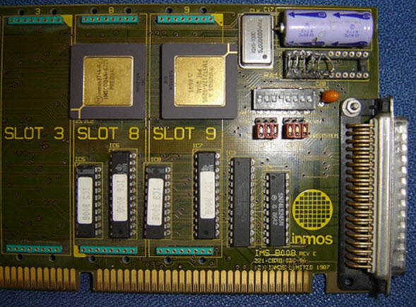
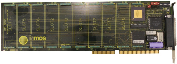
Introduced at the sunset of the Transputer era, the INMOS B008 was the successor of the B004 of which it dramatically differed:

  • 16-bit ISA connector (for Interrupts/DMA, it’s still an 8 bit data path)
  • 10 TRAM slots
  • C004 and T2xx on board

The usual source provides the full manual/documentation… down to the GAL equations.
All these enhancements enabled the B008 to create simple, yet powerful Transputer networks on a single expansion card and still makes it the perfect platform for todays Transputer retro experiments/fiddlings.

Here’s a late “Rev.F” version of the IMSB008:

IMSB008E

The previous revision E had a ceramic version of the T2xx and used GALs instead of the CPLD you can stop in aboves picture.

B008_revE

Clones

Obviously the Inmos B008 had clones as the B004 did.

Transtech TMB08

Well, I guess there’s nothing which Transtech did not clone and/or improve…
In this case they used a AMD MACH CPLD from the beginning, a PLCC version of the T225 and everything else was SMD.

TMB08

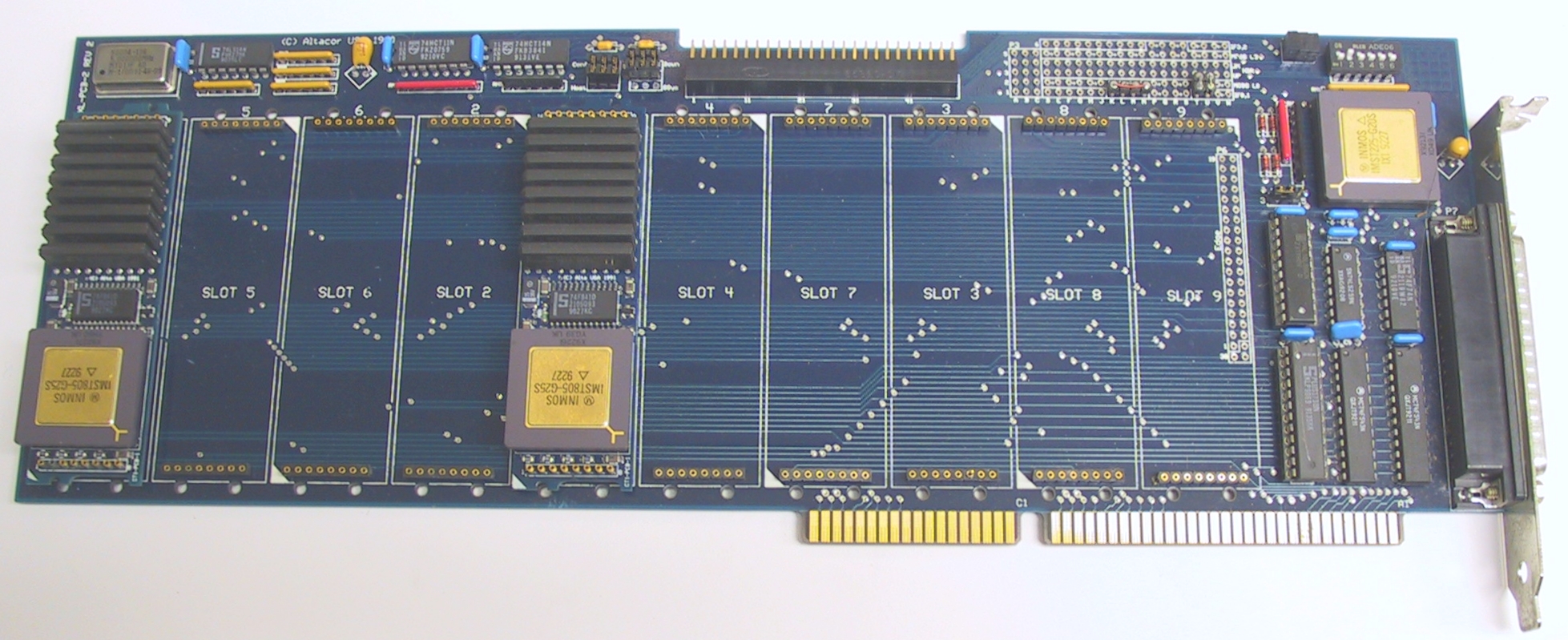
Alta SuperLink/XL Transputer PC Card

Alta Technology was a spin-off of Computer System Architects (CSA).
The SuperLink/XL board used TRAM modules like the Inmos B008, but featured a 20 MHz IMST225 Transputer to handle external interfacing and a beefed-up host interface design. Like the B008 it supported 10 TRAM’s

Altacor SuperLink XL

ARADEX

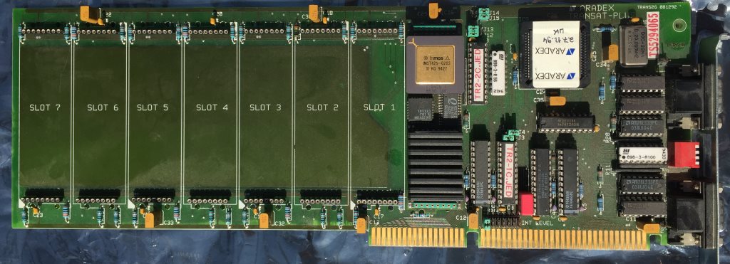
One of my first TRAMs was an ARADEX one, so this is a first for me, too. Actually I wasn’t aware that ARADEX also made TRAM carriers… but they seem to do quite some:

TransAT Plus

Their interpretation of the B008 theme features just 8 TRAM slots (vs. the 10 “standard”) which are strangely enough sorted in ascending order (0-7) and not like the B008 order of 1, 5, 6, 2, 0, 4, 7, 3, 8, 9. Also the TransAT provides two 9pin D-subminiature connectors in contrast to the B008s 37pin connector – most likely its layout is the so called Aalener Link-Interface. That includes the RS-422 differential drivers and receivers next to the connector (AM26LS23’s and AM26LS33’s).

Concerning other parts, besides an C012 they used some sort of CPLD – presumably to control the 16 bit bus – in the photos I have, I can clearly see the traces coming form the ISA Bus’ D[8-15].
It also uses the IRQs 10-12.

Last fun bit: They named the two GALs with their JED filenames. Very handy 😉

aradex_transat-plus

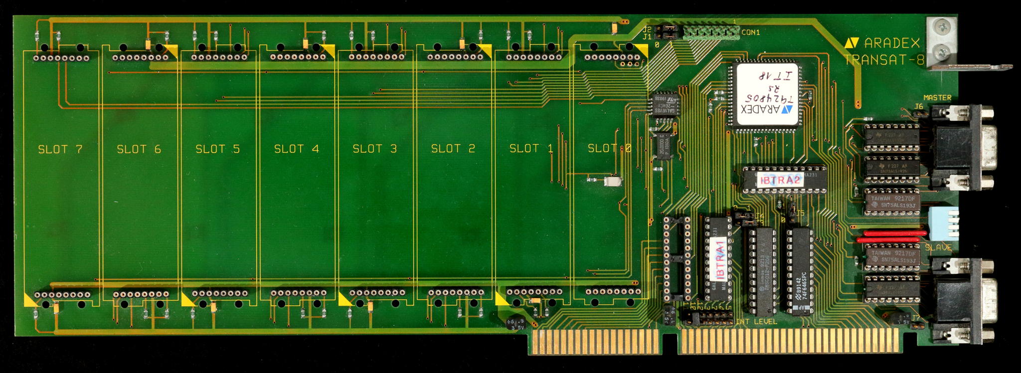
TransAT-8

The “8” in its name makes it a valid member of this collection – but it misses an C004 and also has just 8 TRAM slots… so maybe it should be considered somewhere between an IMSB004 and B008?

This time TIs 74ALS192/193 differential drivers are used, the PLCC chip is yet unknown… and in this case, a TTL chip (next to the ISA slot) is missing… all in all, it looks like a refresh of the TransAT Plus to me.

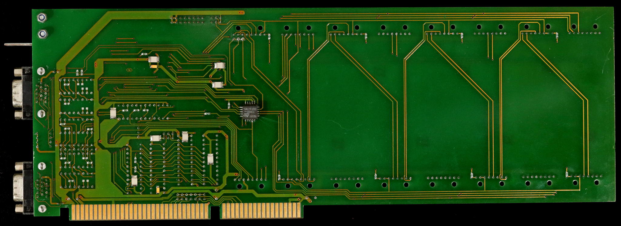
I even have a piccy of the back-side. Why the heck is somebody putting a GAL there?

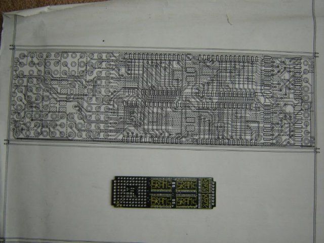
Deciphering the INMOS IMSB430

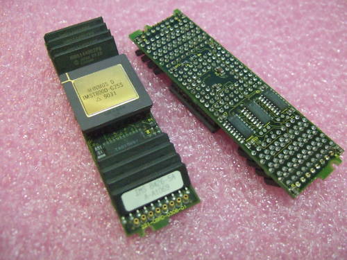
The IMSB430 is a rare, yet interesting and important TRAM. It’s been meant for hardware developers to easily build and test prototypes before producing actual PCBs.

Interesting enough, next to no documentation besides a sales brochure has survived. So it’s time for reverse engineering… again. This is also an official call for help – If you by any chance know more about this TRAM, please contact me!

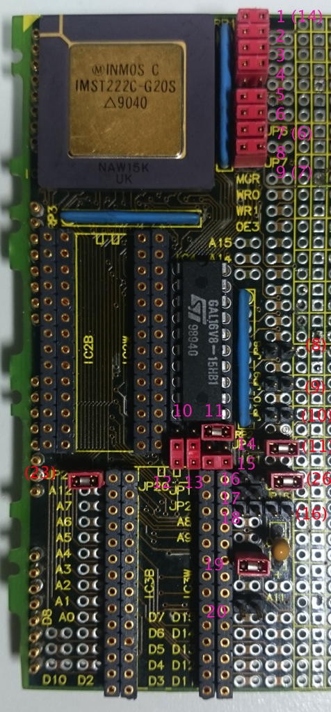
Here’s the left side of this size-4 TRAM. The other half is just the prototyping grid with lots of through holes which we can omit here.
I tried to number all jumpers on the board starting at the top – numbers in brackets are the jumper-numbers actually printed on the boards silk-screen. That numbering is a bit confusing and seems not to follow any logic.

IMSB430 Map

IC connections

Buzzing through all lines from/to the GAL leads to this table so far:

1 ProcClkOut 20 VCC
2 A13 19 Mem0 (IC2B „/CE“ + JP26)
3 A14 18 Mem1 (IC3B „/CE“ + „J20“)
4 A15 17 1Wait (IO 2-above JP8)
5 notMemCE 16 2Wait (IO above JP8)
6 WaitSEL0 (JP8) 15 3Wait (IO below JP8)
7 WaitSEL1 (JP9) 14 SelWait (MemWait+ IO below JP9)
8 Map0 (JP10) 13 BLK0 (IO below JP10)
9 Map1 (JP11) 12 BLK1 („IO1“ below JP11)
10 GND 11 (I/OE) GNDed

Each SRAM socket is actually a “double row”.
If you seat your SRAMs aligned to the right, they will be accessed word-wide (16bit, D0-A15). When aligned to the left, they are accessed byte-wide (8bit, D0-A7). That’s why the silkscreen print says “IC2B/IC2W“…

Jumpers

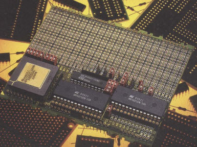
This is the official press photo. It seems to show the default jumper settings (using the full 64KB SRAM, word-access):

IMSB430_official

Some jumpers are already identified (“JP” precedes the official jumpers, “J” is my numbering):

Jumper description
 1  MemWait (FIT=GalPin14, else ????)
 2  DisIntRam (FIT=use internal RAM)
 3  ProcSpeedSel0 (FIT=HoldToGnd T222)
 4  MemReq (FIT=no request)
 5  EventReq (FIT=no request)
 6  MemBacc (FIT=word access)
 7 (JP6)  ProcSpeedSel2 (FIT=HoldToGnd T222)
 8  BootFromRom (FIT=BootFromLink)
 9 (JP7)  ProcSpeedSel1 (FIT=HoldToGnd T222)
JP8 Set MemWaitstate Bit0
JP9 Set MemWaitstate Bit1
JP26 Connects /OE with /CE of IC2 (upper SRAM)
J20 Connects /OE with /CE of IC3 (lower SRAM)

The external RAM access wait-states can be set with JP8/9:

JP8 + JP9 = 2 clock-cycles per MemAccess
JP9 = 3 clock-cycles
JP8 = 4 clock-cycles
none = 5 clock-cycles

To be continued…

Inmos B004

I’d call the Inmos B004 the “mother of all Interface cards”, simply because it was the first ISA card sold by INMOS. And it wasn’t just the card but it also defined the (PC) standard of the software interface, mostly called the “B004-interface”. What a surprise 😉

So being the first card, it is quite big (full ISA length) while not offering really impressing specs: 8bit XT Bus, just one Transputer –TRAMs weren’t invented yet- and a max. of 2MB RAM (DILs). To do it justice, the manual rightfully calls it “Evaluation Board” and for that purpose it’s totally fine – remember that 2MB were quite an amount of RAM back in 1984.
To create a multi-Transputer network you had to either plug-in multiple B004s or connect an external network to the onboard connectors (the blue ones in the picture below).

As mentioned, the B004 software interface is what makes this card a keystone in the Transputer universe. All communication to the host (i.e. the XT/AT compatible PC) is done through a port range normally beginning at 0x150 (base, can be moved by some cards).
With certain offsets the host software can communicate with the Transputer, or the C011 to be precise:

Base Address Register Comment
+0x00 C011/12 input data  read
+0x01 C011/12 Output data write
+0x02 C011/12 input status register read = returns input status
write = set input interrupt on/off
+0x03 C011/12 Output status register read = returns output status
write = set output interrupt on/off
+0x10 Reset/Error register write: Reset Transputer & C011/12 and possibly subsystem (check manual)
read: Get Error status
+0x11 Analyse register  (un)set analyse

This mapping was used by more or less all ISA interface cards and extended by other more sophisticated interface cards later.

Clones

Needless to say, that very soon there were a couple of “inspired” models from other manufacturers. AFAIK all of them support Transputers up to 30MHz, which the B004 didn’t… so they’re actually better.

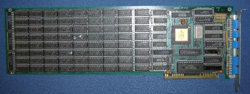
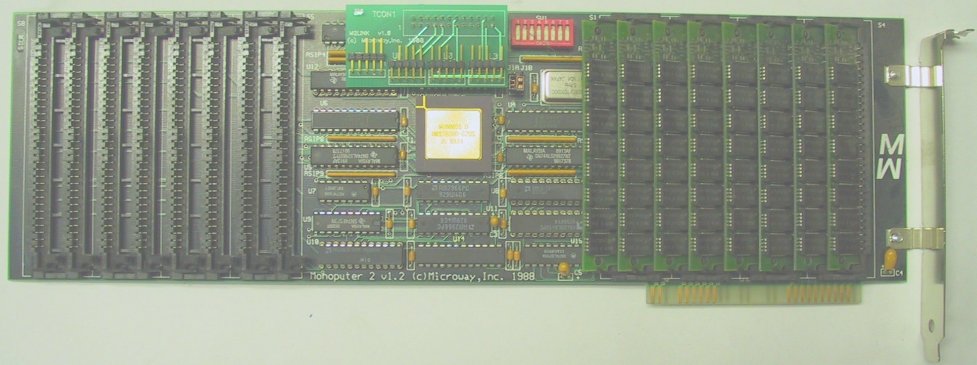
This example is from Microway (yes, those guys who later build the i860 Number Smasher), named Monoputer and dated 1987. Up to 2MB could be used on it. Mind the connectors being accessible from the outside:

Microway-B004

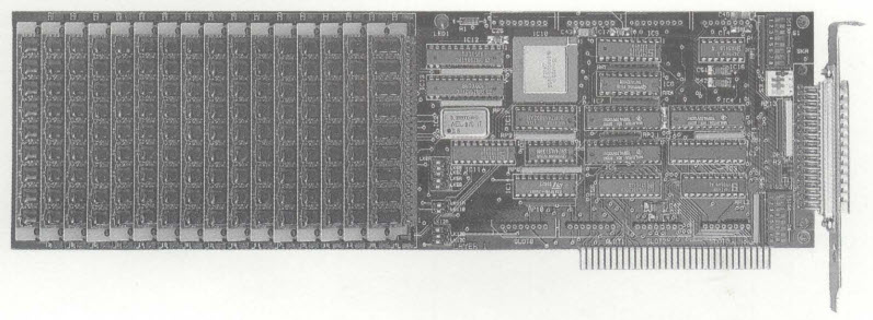
Later they produced the “Monoputer 2” which was more modern and used SIMM RAM modules instead of DIL parts. The Transputer and Linkinterface moved into the middle of the card and the link connectors were moved inside the pc case again – the connectors are the very same used on the NumberSmasher860:

monoputer2

And here’s the one Transtech made, calling it TMB04 mind the SIMM banks which enable the card to give home up to 16MB RAM (at 3 cycle speed!):

Transtech TMB04

Transtech TMB316

The Transtech TMB316 never really seemed to see the light of day and is probably one of the last Transputer developments of AG Electronics for Transtech. Internally it’s also been called the “MTPA-0001”, MTP translates into Multi Transputer Platform, most likely “A” for 2MB and version 0001.

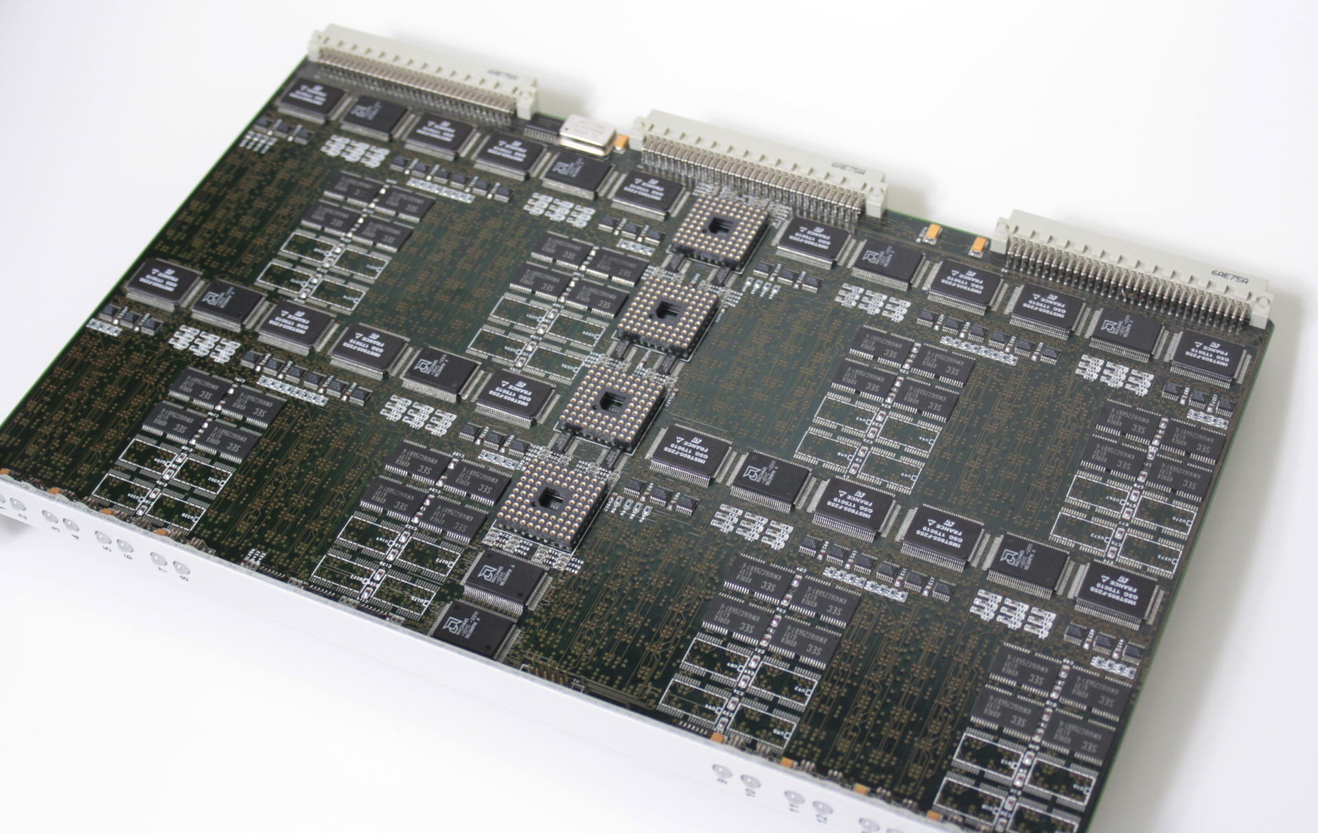
It’s a triple-height Eurocard board featuring 16 T805 at 25 or 30MHz, each with 2 or 4MB RAM. This is the card in full beauty:

TMB316_total

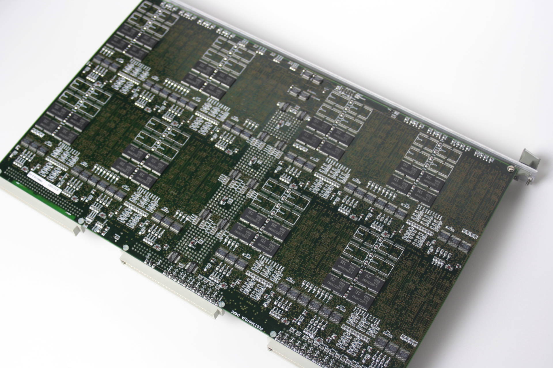
As you can see, it’s not totally cramped with parts and actually has quite uncongested areas. The reason for that is, that this model (Called TMB316-2-25) only uses 2MB of the possible 4MB RAM per Transputer and while all Transputers are placed on the top side of the PCB, every second Transputer has its RAM on the bottom side, right beneath the ‘free space’ visible on the top. This is the back side (flipped horizontally):

TMB316_back

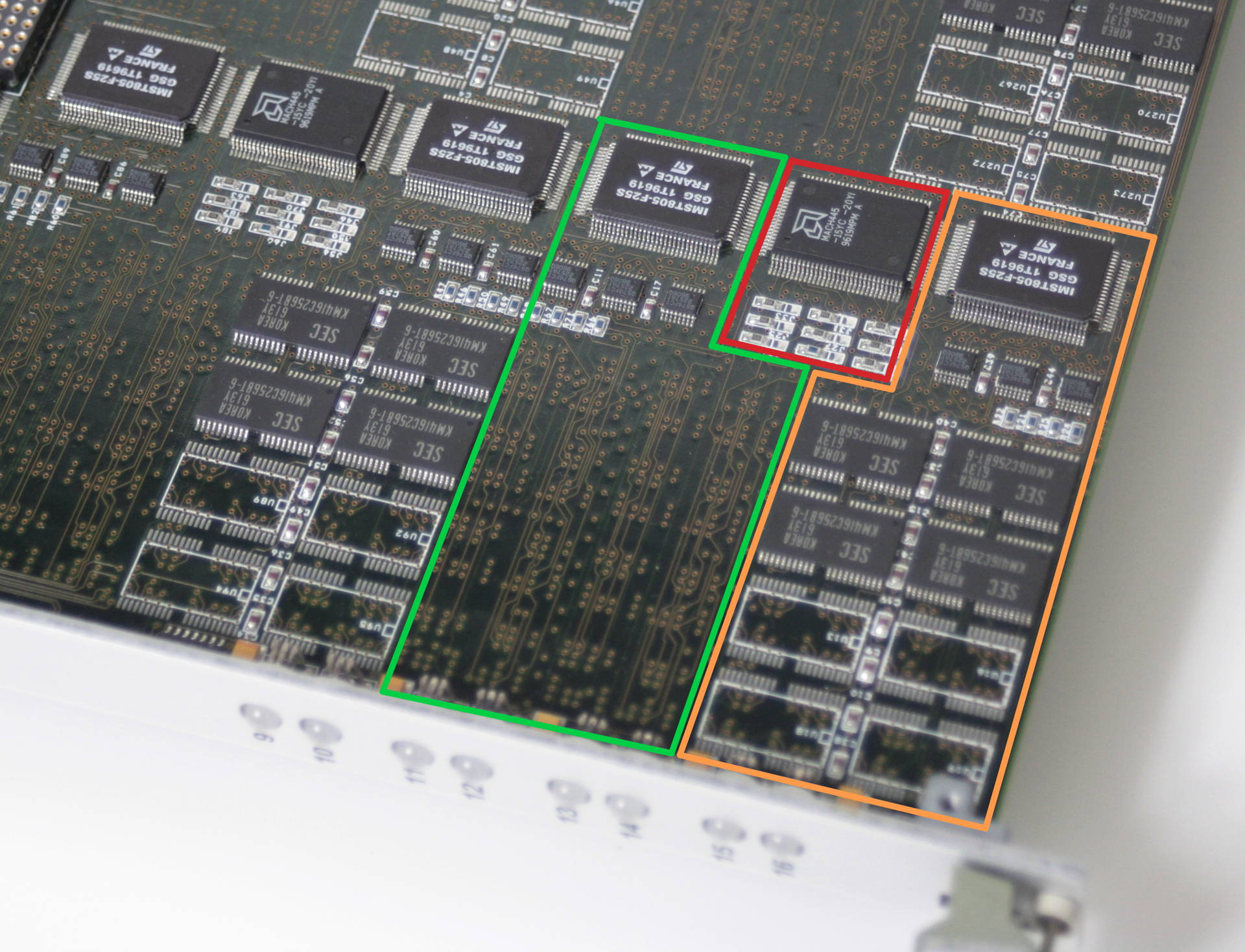
It becomes more obvious, when we zoom into a Transputer section of the board:

TMB316_nodes

I coloured each Transputer (green and orange) with its RAM area. The red area shows the CPLD which is shared between the two Trasnputers and handles the DRAM control and such.
Also visible on the cards front panel are 8 of totally 16 LEDs which display each Transputers status.

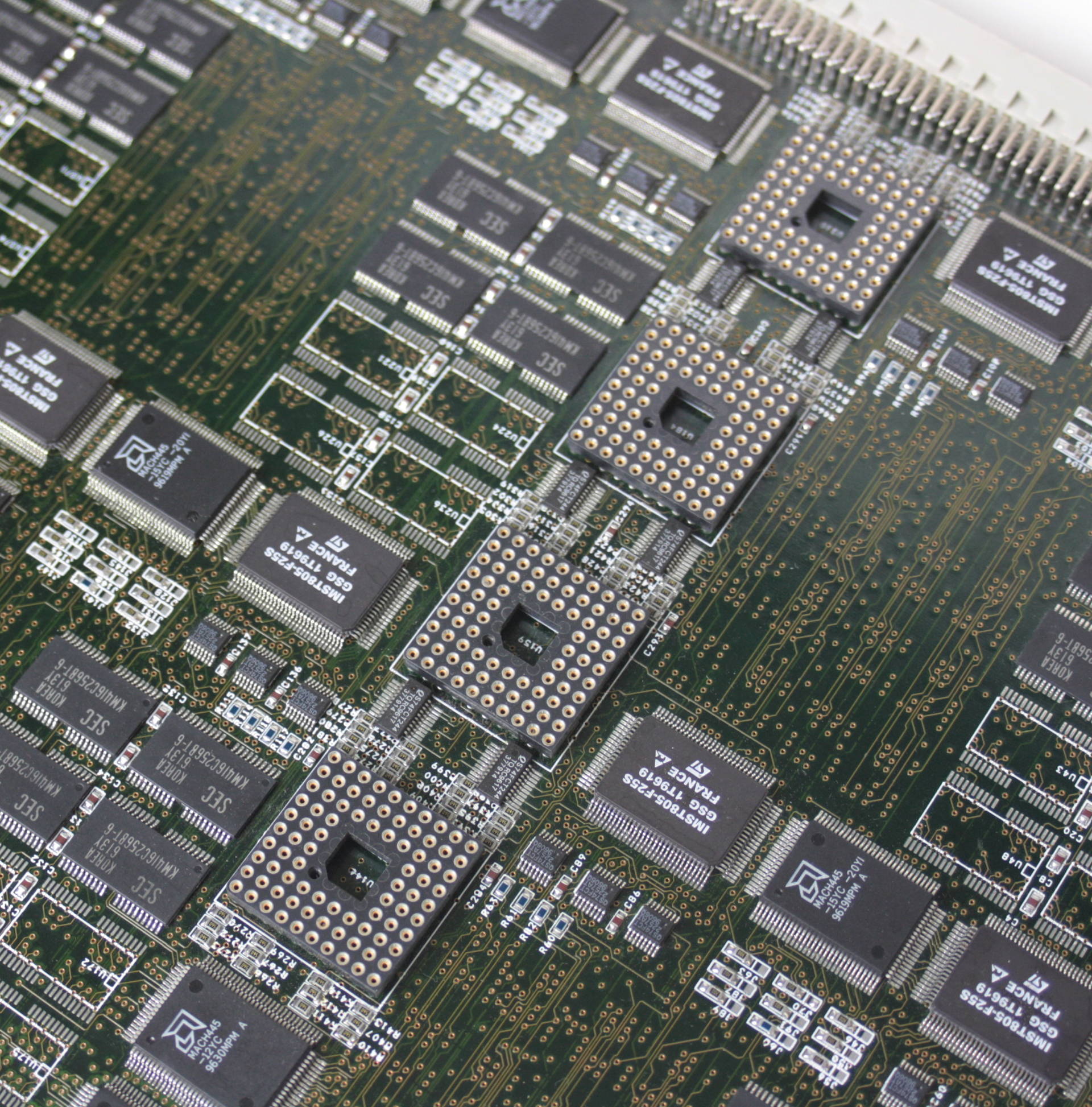
Obviously meant for a bigger systems, Transtech/AG Electronics planned the TMB316 for big deployments, i.e. more than one card. So each card uses four C004 link switches which connect the 16 T805 to each-other as well as to the outside world via the DIN connectors at the back of the card (totally non-standard pinout). This is fine if reconfiguration of the T-network is important but there’s no alternative but using dummy PCBs if all you need is speed. And being an avid GeekDot reader, you know my view on C004’s 😉

TMB316_C004This is where the C004s were meant to live.

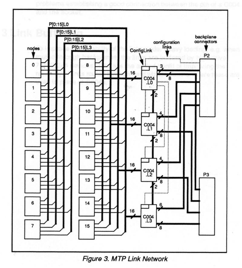
Just in case you really want to know, here’s how the Transputer nodes are connected to the 4 C004 and to the backplane connectors:

TMB316_C004_links

Basic Transputer Tools

Ok, so you have your shiny (not so) new Transputer system installed/connected and you really like to know if it works and at least see some results… you’re in need of basic Transputer tools to get started.

First, download the Geekdot “Transputer Tool Kit” from my Transputer software page (New releases are possible, mind the version number).
Each tool introduced here has its own folder in the archive.

ispy/mtest

Even it’s historically not the first application ever developed for Transputers it’s for sure one of the most used.
It started as ‘check‘ and at some point got renamed into ‘ispy‘ – whatever the name is, the technical term would be “network worm”. This means it’s a special piece of code which a) sniffs around in a transputer (what kind, number of links and their speed) and b) replicates itself over all links it previously found.
When done, it outputs a network map like this example:

Using 150 ispy 3.23
 # Part rate Link# [ Link0 Link1 Link2 Link3 ] by Andy!
 0 T800d-25 292k 0 [ HOST   ...   ...   1:0  ]
 1 T425c-20 1.6M 0 [  0:3   2:0   3:0   ...  ]
 2 T400c-20 1.8M 0 [  1:1   ...   ...   ...  ]
 3 T400c-20 1.7M 0 [  1:2   ...   ...   ...  ]

ispy is used on geekdot.com extensively, so any time I write about Transputers you will see some sort of ispy output for sure.
There are several versions of ispy included in this kit. This is because some versions behave more stable than other in certain circumstances. E.g. the most recent version 3.23 does not work very well with the C004 link-switches.

“The other part” of ispy is called mtest. mtest takes ispys output and runs an indepth memory test/report on all Transputers found.

iserver

iserver is part of what INMOS called “itools” – long before Apple discovered the “i” for themselves 😉 – there were many others, mainly development focused (e.g. idebug, icconf etc.).
It is more or less the successor to the godfather of all Transputer booting tools “afserver” (1988). Well, it has to be, being the on INMOS supplied with all their other tools and languages.
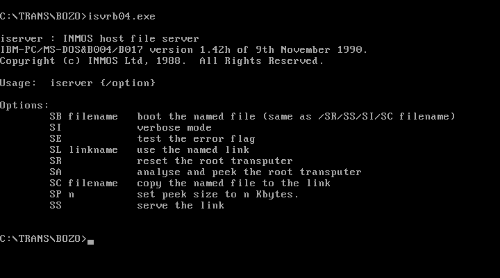
The possible options are quite self-explanatory and printed to stdout when omitting any option:

iserver142h

Basically if you see a *.btl, *.b4 or *.b8 file it’s most likely meant to be executed with iserver. Before running successfully iserver need some environment variables set to successfully to be used:

set IBOARDSIZE=#100000
set TRANSPUTER=#150

These two settings tell all itools how much RAM the Transputer has to work with and at which port address it can be found (0x150 is default anyway). The archive contains V1.42h from Nov. 1990 which is the most recent as far as I know.

Mandelbrot

The “CSA Mandelzoom Version” is one of my favorite benchmark tools. I like it so much, that I run it once a while just for fun.. and to extend my benchmark table which I’ve collected over the time using it.

It is nice because it features integer (T4xx) as well as floating point (T8xx) versions of the calculation ‘slave processes’ and scans the network itself. No external tool needed. It’s also possible to let the host (i.e. your PC) calculate the Mandelbrot fractal to get an idea, how much faster/slower your Transputer network is – the archive contains a little benchmark result text file which I accumulated over the years.
Also there are some handy switches available (‘-h’ for help):

  • -v : Use VGA graphics
  • -t : Run on host instead of Transputers
  • -a : Autozoom, loads  a list of coordinates from man.dat and start calculating them without manual interaction.
  • -b : Use a different base address (instead 0x150)
  • -x : Verbose output of the Transputer initialization process (added by me)

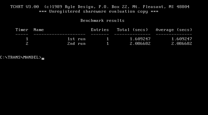
After a while I got tired of manually time a calculation run and also ran into problems with large networks which simply became to fast to hand time. So I extended the code of Mandelzoom with a high precision timer (TCHRT, shareware, can’t remove the splashscreen, sorry) which prints out a timer summary when run with the “-a” parameter. I provided my default “MAN.DAT” file, which contains 2 coordinates to calculate (1st & 2nd run) and used for all my benchmarks.

csa_mandel_timerThese are the results of my DOS host system running in VirtualBox.

Caveat: It breaks if there’s a T2xx in the network (e.g. B008/B012) 🙁 And as always: Read the F-ing README.txt!

Since I started to heavily modifying the source, I wrote a post of its own about it as well as put everything on github, so you can join the fun 😉

Other Tools

iskip

iskip can be very handy, when ‘talking’ directly to (externally) connected links, e.g. another network which is connected to your root Transputer. Here’s a good example:
You like to put code directly onto “processor 1” which is connected to link 2 of your root Transputer:

iskip

So you call

iskip 2 /r /e

This sets up the system to direct the program to the target network over the top of the root transputer and starts the route-through process on the root transputer. Options ‘R’ and ‘E’ respectively reset the target network and direct the host file server to monitor the halt-on-errorflag. The program can then be loaded ‘through’ the root Transputer directly onto processor 1 using:

iserver /ss /se /sc test.btl

debug.exe

Yes, I do mean the comes-with-DOS debug.exe. Well, you can use any debugger you like as long it can read/write to port addresses.
Obviously this means [MS|PC|Open|Free]DOS only. You won’t get far with this on Linux, any Windows or OS/2. At least for initial debugging and testing I strongly recommend to use the “bloated interrupt manager” known as DOS.
First of all, you have to know the port addresses the C012 registers are mapped to . There’s a de-facto industry standard which INMOS introduced with the IMSB004. Its been adopted by 90% of all 3rd party products, even with certain ISDN cards using Transputes.

The base address normally is at 0x150 (which can be configured to other addresses in some cases). From this base adress the offset is always the same:

Base Adress Register Comment
+0x00 C012 input data  read
+0x01 C012 Output data write
+0x02 C012 input status register read = returns input status
write = set input interrupt on/off
+0x03 C012 Output status register read = returns output status
write = set output interrupt on/off
+0x10 Reset/Error register write: Reset Transputer & C012 and possibly subsystem (check manual)
read: Get Error status
+0x11 Analyse register  (un)set analyse

So here’s a clean Transputer setup ‘conversation’ using debug (comments are just for clarity, not supported in debug):

c:\>debug
 -o 160 1         # Assert RESET
 -o 161 0         # Deassert ANALYSE
 -o 160 0         # Deassert RESET ... init B004/IMSC
 -o 152 0         # Clear Input  Interrupt enable
 -o 153 0         # Clear Output Interrupt enable
 -i 152           # Read Input Status
 00               # Bit 0 = 0 -> no Data waiting
 -i 153           # Read Output Status
 01               # Bit 0 = 1 -> ready to send 
 -i 160           # Read Error
 00               # Bit 0 = 0 -> ERROR not signaled
-o 151 1          # send POKE
-i 153            # Read Output Status
01                # Ready -> POKE Ack (00 = BAD no Transputer) 
After that you’re fine to send and receive bytes through 0x151/0x150. Doing so, you’re completely free which programming language to use. Here are some examples in AppleSoft Basic or even Python.

The Inmos C004

Hardware

Before I reinvent the wheel, here’s the quick intro from the manual, what an Inmos C004 actually is:

The IMS C004 is a transparent programmable link switch designed to provide a full crossbar switch between 32 link inputs and 32 link outputs. The IMS C004 will switch links running at either the standard speed of 10 Mbits/sec or at the higher speed of 20 Mbits/sec.
It introduces, on average, only a 1.75 bit time delay on the signal. Link switches can be cascaded to any depth without loss of signal integrity and can be used to construct reconfigurable networks of arbitrary size. The switch is programmed via a separate serial link called the configuration link.

So in simple words: 32 inputs can be freely connected to 32 outputs. Great for large Transputer networks which can be reconfigured only by reprogramming the C004 – on top of that, you can cascade them and create huge, complex networks to make any connection imaginable possible. Like those Parsytec used in their SuperCluster machines looking like this:
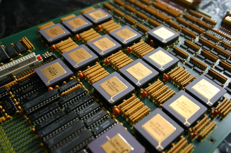
MegaFrameXbarDetailYes, that’s 13 C004s and one Transputer to rule them all…

… so much for the theory.

In practice, the C004 is a bitch. Not only does it require a Transputer to configure it (normally a 16bit T2xx) it also adds quite a delay into the link-communication. As mentioned above, it’s “only a 1.75 bit time delay” but this can sum up to quite an amount.
Let me quote some more realistic numbers from the Helios manual (pp.255):

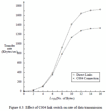
It is of interest to ascertain the effect of the Inmos C004 on the performance of the Helios communication mechanisms. Figure 6.3 illustrates the rates of data communication (Kbytes/second) attained using message passing primitives (PutMsg() and GetMsg()) between two Transputers that were
1. Directly linked and
2. Connected through a C004 link switch.
It is evident from Figure 6.3 that the effect of the C004 link switch on the rate of communication is far from negligible. The overhead imposed by the link switch increases with the size of the message. In the worst case (64 Kbyte message), transmission through the C004 is 23 % slower than sending data over directly connected links.
C004_helios

Oops. 23% is quite essential. So before planning to set up a crazy C004 network you might consider what you want to achieve.
Is it for educational network studies only? Fine.
Are you going for speed and rarely change your Transputer network configuration? Avoid it!

IMHO even the 10 possible Transputers on an IMSB008 do not require a C004 making your day.
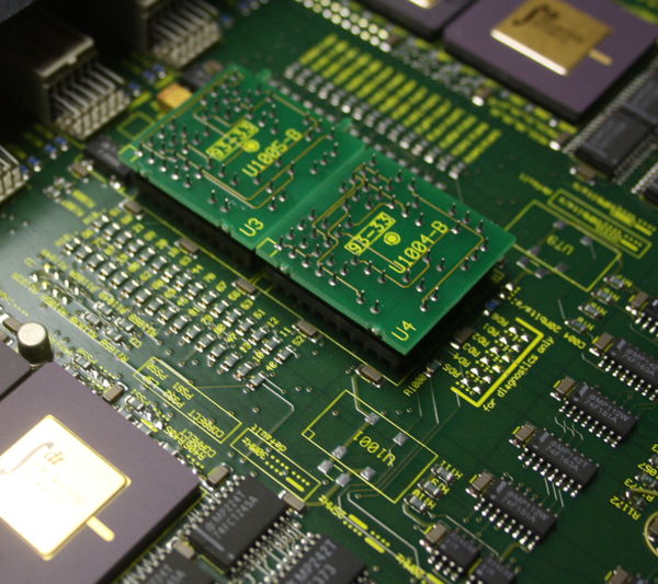
Actually, even Parsytec thought that this is useless to use a link switch for the 16 Transputers in their beautiful x’plorer and replaced it by hard-wire dummies:
C004_dummies2

Configuration

Ok, you’re still not scared away and really do like to know how to handle that beast. Fine, here’s what I went through:

To work with a C004 you obviously need either a TRAM carrier like the B008 or some sort of motherboard like the IMSB012 or IMSB014.  Read the boards manual to understand how to connect to the T2xx Network Control Processor (NCP).
For example the IMSB012 has extra pins for “config down” (i.e. IN) and “config up” (i.e. OUT) for its T212 and any other boards being chained to it.
As for the IMSB008 has its T222 connected to Link 1 of TRAM 0.

The hardware wiring is important to know, because this information is needed for the so-called hardwire file used by the INMOS tool “MMS2” (Module Motherboard Software, MSDOS only, the manual is available here).
After reading the manual (do!) you should be able to read this hardwire file for an B008 quite easily. It describes the complete hardware setup and all physical connection between the C004(s), T2xx and Transputer/TRAM links on the board:

-- B008 hardwire description
DEF B008
  SIZES
    T2 1
    C4 1
    SLOT 10
    EDGE 10
   END
   T2CHAIN
     T2 0, LINK 3 C4 0
   END
   HARDWIRE
     SLOT 0,LINK 2 TO SLOT 1,LINK 1
     SLOT 1,LINK 2 TO SLOT 2,LINK 1
     SLOT 2,LINK 2 TO SLOT 3,LINK 1
     SLOT 3,LINK 2 TO SLOT 4,LINK 1
     SLOT 4,LINK 2 TO SLOT 5,LINK 1
     SLOT 5,LINK 2 TO SLOT 6,LINK 1
     SLOT 6,LINK 2 TO SLOT 7,LINK 1
     SLOT 7,LINK 2 TO SLOT 8,LINK 1
     SLOT 8,LINK 2 TO SLOT 9,LINK 1
     C4 0,LINK 10 TO SLOT 0,LINK 3
     C4 0,LINK 1 TO SLOT 1,LINK 0
     C4 0,LINK 11 TO SLOT 1,LINK 3
     C4 0,LINK 2 TO SLOT 2,LINK 0
     C4 0,LINK 12 TO SLOT 2,LINK 3
     C4 0,LINK 3 TO SLOT 3,LINK 0
     C4 0,LINK 13 TO SLOT 3,LINK 3
     C4 0,LINK 4 TO SLOT 4,LINK 0
     C4 0,LINK 14 TO SLOT 4,LINK 3
     C4 0,LINK 5 TO SLOT 5,LINK 0
     C4 0,LINK 15 TO SLOT 5,LINK 3
     C4 0,LINK 6 TO SLOT 6,LINK 0
     C4 0,LINK 16 TO SLOT 6,LINK 3
     C4 0,LINK 7 TO SLOT 7,LINK 0
     C4 0,LINK 17 TO SLOT 7,LINK 3
     C4 0,LINK 8 TO SLOT 8,LINK 0
     C4 0,LINK 18 TO SLOT 8,LINK 3
     C4 0,LINK 9 TO SLOT 9,LINK 0
     C4 0,LINK 19 TO SLOT 9,LINK 3
     C4 0,LINK 20 TO EDGE 0
     C4 0,LINK 21 TO EDGE 1
     C4 0,LINK 22 TO EDGE 2
     C4 0,LINK 23 TO EDGE 3
     C4 0,LINK 24 TO EDGE 4
     C4 0,LINK 25 TO EDGE 5
     C4 0,LINK 26 TO EDGE 6
     C4 0,LINK 27 TO EDGE 7
 -- Uncomment the next two lines if the
 -- patch header wiring is used to
 -- connect C004, link 28 to PatchLink0,
 -- and C004, link 29 to PatchLink1.
 -- C4 0,LINK 28 TO EDGE 8
 -- C4 0,LINK 29 TO EDGE 9
   END
PIPE B008 END

After that’s done, you can prepare a second file. The so called “softwire file” which actually tells the T2xx how to internally connect his in- and out-links. A very simple example would be:

SOFTWIRE 
PIPE 0
 SLOT 0,3 TO SLOT 1,3 
END

This would connect TRAM-0’s 3rd link to TRAM-1’s 3rd link.
Now that you have the necessary config files let’s move on to the MMS itself.

Software

As with nearly every software from INMOS the MMS too is written in OCCAM and therefore has to run on a Transputer. This might be the one in TRAM slot 0 on your B008 or on a local ISA board which itself is connected with 2 links to a B012 (one for config and one to the Transputer network).

To make things easier, I prepared a complete MMS archive to download here (links to my Transputer Software page).
It contains some example soft- and hardwire files, an ISERVER.EXE (the program you need to upload code into your Transputer) as well as a batch file to easily start MMS (RUN_MMS.BAT).
Also you will find a folder with INMOS’ pimped version of ANSI.SYS called BANSI (“Better ANSI”), because all INMOS tools make heavy use of ANSI screen control. So put that into your CONFIG.SYS.

Before we begin, let’s have a look at my IMSB012 with ispy:

ispy 2.33
   # Part rate Mb Bt [  Link0  Link1  Link2  Link3 ]
   0 T800d-25 0.37 0 [   HOST    1:1    2:1    ... ]
   1 T2   -20 1.64 1 [    ...    0:1    ...    ... ]
   2 T800d-25 1.75 1 [    ...    0:2    3:1    ... ]
   3 T800d-25 1.77 1 [    ...    2:2    4:1    ... ]
   4 T800d-25 1.77 1 [    ...    3:2    5:1    ... ]
   5 T800d-25 1.75 1 [    ...    4:2    6:1    ... ]
   6 T800d-25 1.75 1 [    ...    5:2    7:1    ... ]
   7 T800d-25 1.75 1 [    ...    6:2    8:1    ... ]
   8 T800d-25 1.75 1 [    ...    7:2    9:1    ... ]
   9 T800d-25 1.75 1 [    ...    8:2   10:1    ... ]
  10 T800d-25 1.75 1 [    ...    9:2   11:1    ... ]
  11 T800d-25 1.75 1 [    ...   10:2   12:1    ... ]
  12 T800d-25 1.75 1 [    ...   11:2   13:1    ... ]
  13 T800d-25 1.77 1 [    ...   12:2   14:1    ... ]
  14 T800d-25 1.77 1 [    ...   13:2   15:1    ... ]
  15 T800d-25 1.75 1 [    ...   14:2   16:1    ... ]
  16 T800d-25 1.77 1 [    ...   15:2   17:1    ... ]
  17 T800d-25 1.77 1 [    ...   16:2    ...    ... ]

Ok, let’s start MMS2. Use/modify the batch “run_mms.bat” which will do all environment variables expected by iserver.exe and also adds the input and output files – change it as you please.
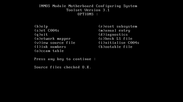
If everything works fine, iserver loads MMS2.B4 onto your Transputer and executes it. Your screen should look like the screenshot below.
First, I suggest you press “c” for checking the consistency of your hard/softwire files – if everything’s fine, MMS2 will print “Source files checked O.K.” as seen in the lowest line in the screenshot.
MMS1

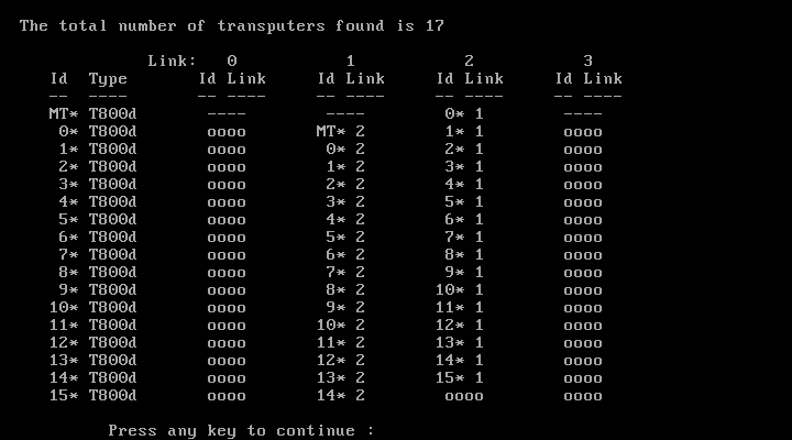
Just for the fun of it, you can try MMS’ very own network worm – so press “n” to start the network mapper. You will see that it is much slower than e.g. ispy, so just be patient.
After some seconds, you should get something like this:
MMS2

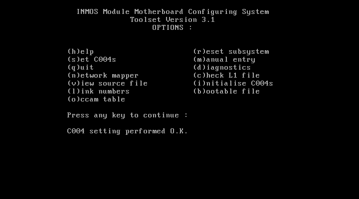
Now it’s time to program you network. So press “s” to set the C004(s). Some infos will rush trough the bottom line of the screen and finally MMS2 states “C004 setting preformed O.K.“:
MMS3

Nothing more to do here so press “q” to quit MMS2.  (Do not run the network mapper again! It seems to reset the T2 and in my case reproducibly crashes the network).
It’s better to use ispy. ispy v2.33 to be precise. I encountered several issues with the C004 and the most recent version 3.23 of ispy.

So running ispy including the /C4  switch to display the settings of the two C004s now shows this – mind all the new connections of each Transputers Link0 and 3:

ispy 2.33
   # Part rate Mb Bt [  Link0  Link1  Link2  Link3 ]
   0 T800d-25 0.37 0 [   HOST    1:1    4:1    ... ]
   1 T2   -20 1.74 1 [    2:C    0:1    ...    3:C ]
   2 C004b   [ 6S3JM54V --U8-1C- -G--F9-I T--7-PQ- ]
   3 C004b   [ -D-2650R BL--E--K H-N3--4- -TU-1OA7 ]
   4 T800d-25 1.65 1 [    ...    0:2    5:1    6:0 ]
   5 T800d-25 1.75 1 [    ...    4:2    7:1    8:0 ]
   6 T800d-25 1.41 0 [    4:3    9:2    8:1   10:0 ]
   7 T800d-25 1.75 1 [    ...    5:2    9:1   11:0 ]
   8 T800d-25 1.41 0 [    5:3    6:2   11:1   12:0 ]
   9 T800d-25 1.75 2 [    ...    7:2    6:1   13:0 ]
  10 T800d-25 1.35 0 [    6:3   13:2   12:1   14:0 ]
  11 T800d-25 1.41 0 [    7:3    8:2   13:1   15:0 ]
  12 T800d-25 1.42 0 [    8:3   10:2   15:1   16:0 ]
  13 T800d-25 1.32 0 [    9:3   11:2   10:1   17:0 ]
  14 T800d-25 1.35 0 [   10:3   17:2   16:1    ... ]
  15 T800d-25 1.41 0 [   11:3   12:2   17:1   18:0 ]
  16 T800d-25 1.33 0 [   12:3   14:2   18:1    ... ]
  17 T800d-25 1.32 0 [   13:3   15:2   14:1   19:0 ]
  18 T800d-25 1.35 0 [   15:3   16:2   19:1    ... ]
  19 T800d-25 1.32 0 [   17:3   18:2    ...    ... ]

Yay! It worked. Positively as well as negatively.
Besides the new connections you might also spot a difference in the link-speed column. In our first run of ispy all Transputers had a link-speed around 1.75MBps.  Now it varies between 1.75 and 1.32, depending on how often the ispy worm crossed a C004.

Two final hints:

If your C004 network has been set-up as planned, you can use ispys output to programm the network later.
Just save the output into an ASCII file (ispy /c4 > my_net.txt) and when needed feed it back into ispy like this:
 ispy /r /cr < my_net.txt
This will reset the network and read in the configuration from stdin.
Obviously you can also manually edit the text file, the c4 lines

   2 C004b   [ 6S3JM54V --U8-1C- -G--F9-I T--7-PQ- ]
   3 C004b   [ -D-2650R BL--E--K H-N3--4- -TU-1OA7 ]

which isn’t as comfortable and comprehensible as editing a hard/softwire file. But your mileage my vary.

Alternatively, MMS2 can create a bootable file with your network settings. This can be used for quickly setting-up your system.
Just hit the “b” key and enter a filename. My MMS2 archive contains the above example as “BOOTB012.BTL”. Run it with “iserver /SB bootb012.btl“.

Caveats

Mind your reset! This means, in many cases a root Transputer might reset all the “worker Transputers” but also your T2xx and in effect all C004. So be careful when resetting your system.

Yes, theoretically you can reconfigure your Inmos C004 on the fly while all connected Transputer run. The most prominent example is having one network topology during data acquisition while changing it for number crunching later on.
This requires a very good knowledge of the notwork and thorough process locking etc.

The Inmos B020

Well, normally I wouldn’t list Inmos’ expansion cards here, as they’re normally just TRAM carrier boards and very well documented at the usual places… but for this card, it’s different.

Not only that there isn’t any documentation of the IMSB020 (just a brochure over at Rams page) but this specific card is an updated version of that described in the brochure… I’d call it Rev.2.
It has a T805 instead of a T4xx and probably some more additions…

Ok, first of all: What is the Inmos B020 anyway? It’s being sold as a “X11 server on a card”… I’m intentionally writing ‘being sold’ because that just one way of usage.
More generally spoken, it’s an ISA card with a Transputer (with 4-12MB RAM) and a graphics controller on it, an Inmos G332 to be precise. That Transputer controls the G322 and can therefore create graphics onto a VGA screen connected to the board.

As an avid reader of GeekDot, this should sound familiar to you because it was the typical 90’s approach of High-End Graphics… see the MiroTiger or the SPEA i860 boards.

With the right software being booted into the Transputer, it may act as a X11 (R4) Server… but it could also used as a native Transputer system, e.g. running Helios or some OCCAM code and still create graphics with the G332 controller. As a nice add-on, the card features two size-2 TRAM slots, so more transputers or devices could be added into the equation.
Ah -and as a side note- most people called the B020 “the BOZO“… not very kind but it gets a credit for its pre-l33tc0de usage.

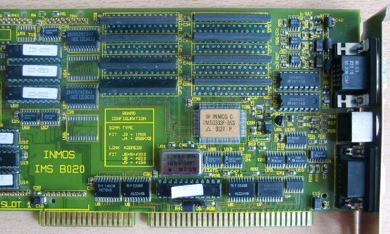
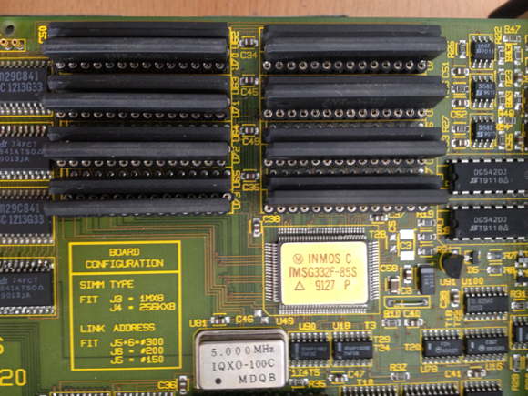
This is how my ‘rev.2’ looks in it’s full glory:

B020full_small

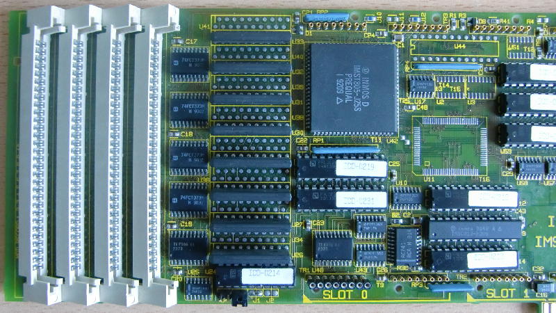
As usual, we go into more detail looking at each half of the card.In this full-view, you can identify the two TRAM-slots by the yellow markings at the lower edge of the card saying “SLOT 0” and “SLOT 1”.

So let’s start with the right half of the B020:

B020right

At the right-most edge, there’s the VGA-in and VGA-out connector, so that you can loop-through the video signal from your regular graphics-cards (a fancy ET4000 for example ;-)).

Between the two VGA connectors is an 8-pin Mini-DIN connector, which has this pinout:

1 Error/ (in)
2 Analyse (out)
3 Tram2 Link 2 out
4 Ground
5 Tram2 Link 2 in
6 Onboard T800 link1 out
7 Reset (out)
8 Onboard T800 link 1 in

The upper 2/3, starting with the golden IC (IMSG322F-85F) is all graphics part. Which consists of the G322 controller, 1MB VRAMabove him and some latches and 3 PALs on the left of it.
Below the G322, next to the slot-connector is the ISA interface. That’s handled by a PAL (with the sticker peeling off) and 4 buffers/transceivers and a bit more “chicken food” around them.
Of course there’s also the inevitable 5MHz oscillator which is needed in every Transputer household.

Let’s move to the left half of the card:

B020left

This is ‘where the music plays’. At the lower edge of the right side you can spot the C012 guarded by two PALs (with white labels) who handles the ‘Bus data-to-Transputer’ translation. The two PALs are most likely the subsystem (i.e. handling Reset, Error, the 012’s RS0/1 registers etc.).
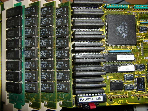
Then there is the King of the Hill, the Transputer himself – a T805-25 in a quite rare PLCC packaging. To his left are 4MB of RAM in ZIP-packaging, most likely configured and controlled by the two PALs below him.
Finally, there are 4 SIMM slots to expand the Transputer memory further to a whopping 8MB! As you can easily see, there are unpopulated solder-pads between the ZIP-RAM ICs (as well as the VRAMs). My assumption is that you could order this card with 8MB soldered, which lead to a max. RAM of 12MB, like mentioned in the brochure on Rams page. But I fear the PALs of the RAM-subsystem need to be programmed accordingly to support the larger amount of RAM (added later: And boy was I right!).

So much for the theory of the B020… and it might stay so for some time, because my B020 is was broken 🙁

But I’m working on it and one fine day you will see an X11 server in an XT-PC at blazing speed 🙂

B020LA

Resurrection

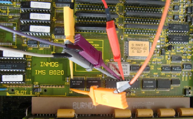
[Nearly 4 weeks later…] As promised, I worked hard on getting the BOZO back to life. It started with weeks of tracing connections of the complete bus-interface, ie. ISA-Bus to the buffers/transceivers, the PAL next to the ISA-bus, the C012 link-adapter etc.etc…
Then, knowing the signals now, came days of staring at the logic analyser, many many mails with Mike Brüstle and lots of hacking with DOSes debug.exe.
Finally it became clear that the PAL 0211 was somehow “confused” and therefore not controlling the bus as it should do. Because there’s no documentation neither of the B020 nor of its PAL equations (like there is for e.g. the B008) I had to go the long and bitter route of reverse-engineering.

So first thing is to remove the faulty part which proved to by a bit tricky – which is a short story of its own available in the DIY-section of this page.
So in went a proper socket and a copy of the original PAL (now a “modern” GAL). The copy proved to be a 100% one… which means not working as it should. But somewhat different than the tries I did before…it was erratic. For example only on I/O port 0x200 I was able to get something useful out of the signals (eg. a well timed /OE for the ‘244 buffers) while jumpering the IO range to 0x150 or 0x300 gave total silence. So I went one step closer to the bus, listening to what the PAL gets on its A4-A11 lines.
There you go! A4-A6 were constantly high and A7 glitching while A8-A11 was happily bouncing. According to my tracing A4-A7 were handled by a different ‘244 than those working. So Sauron turned his eye on the little SMD octal buffers… out went the solder iron and all pins of all buffers were re-soldered.

Lo and behold, the next ispy run on 0x200 worked! Heureka!

Next up: Why is it working on port 0x200 only? Learning from the ‘244 issue I checked all solder-pads concerning the jumper for port 0x150 (that’s J5). Everyhing looked nice and re-soldering didn’t change a bit. So it was the PAL who was suspicious… again.
Luckily INMOS refrained from setting the protection fuse on the PAL, so not only I was able to copy it but also the read its programming. I was thinking about recoding the whole thing and started doing so when I stumbled across a missing “.oe” (Output Enable) for exactly that input-pin connceted to the J5 jumper. So quickly adding

/f14 = gnd
f14.oe = gnd

to the code, compile, burn, plug it into the socket. Tadaa! The B020 now also talks to 0x150… and 0x300 respectively.
[BTW: This happened right at the 30th birthday of DOS. Don’t know if it’s a good or bad sign… at least DOS is my favourite debugging tool 😉 ]

For those who happen to have the same issues with their B020 (erm, that’s probably 1-2 people on this planet by now), here’s my documentation and .jed file for the “PAL 0211B”.

Enhancement

Well, as said in Axels 10 commandments: “Thou should not leave a socket unpopulated!”
And my B020 has a lot of ’em. So I started with the Transputer RAM.
In preparation I checked if the empty solderpads (as you can see in the above pictures) do get all the required signals… well, kind of: I was lazy and just checked /OE with my logic analyser and there was a signal in sync with the one of the already installed RAM. Also all Data- and Addresslines were connected… so it was worth a try!

But I should have known it before: After clearing all 160 pin-holes from the solder, puting self-made zig-zag sockets in place and filling them with the appropriate 1Mx4 RAM chips ispy/mtest still reported just 4MB of RAM :-/

Obviously PAL0214, sitting right below the ZIP RAM was playing an important role here. So the good old routine of “buzzing it through” began. After 2 days I pretty much figured out the purpose of each pin of PAL0214. Yes, it must be the RAM decoder.
So there was no way around removing, reading and replacing it… like with PAL0211.
This time I got myself a desolder-gun – a hell of a facilitation! Again, luckily the PAL wasn’t protected so reading it wasn’t an issue.
As expected, the decoding for the 2nd RAM bank was missing – no idea where the initial measured /OE signals came from.
After the decoding of 1st 4MB ZIP RAM the SIMM RAM followed immediately – so I had to squeeze in the 2nd bank of 4MB ZIP RAM and let the SIMM RAM follow after that. Even my VHDL/PAL Equation skills are quite limited it wasn’t as hard as I expected. Compile, program, put the new GAL16V8 in place, start ispy/mtest, cross fingers….

Using 150 ispy 3.23 | mtest 3.22
# Part rate Link# [  Link0  Link1  Link2  Link3 ] RAM,cycle
0 T805d-25 340k 0 [   HOST    ...    ...    ... ] 4K,1 12284K,4;

Yay! 12MB including the SIMM RAM!! Here’s the view of a “BOZO to the MAX” 😉

BOZO_full_RAM

Double the VRAM!

The last step in bringing the BOZO “to the max” was adding more VRAM, i.e. 2MB.
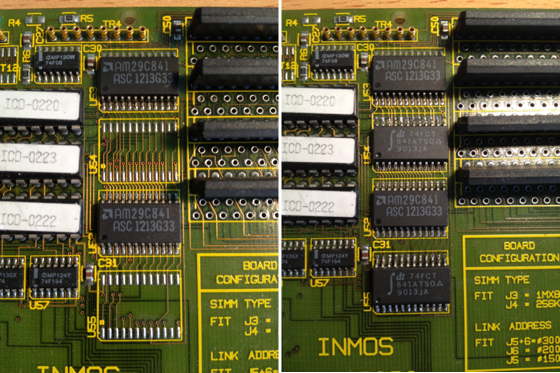
So first you have to get two more AM29C841 9-bit latches (or compatible parts, like those 74FCT841 I’ve used) in SO-24 package. That SMD package is still quite easy to solder onto the board. Here’s a before-and-after picture:

BOZO_VRAM1

On the right-hand side of the latches you can already spot the empty solder-holes for the VRAM. Like with the DRAM expansion before, I made my own sockets by using two 1×14 pin sockets. This is what the now fully populated VRAM section looks afterwards:

BOZO_VRAM2

The first run using “ixcheck” from the INMOS iX package went without errors and the /OE signals of all the ‘841s are driven correctly according to my logic analyzer. I was a bit scared that INMOS might have again not completely programmed the PALs (left to the latches) to support this memory expansion but it seems I’ve been lucky.

Next up: Find a tool using the 2MB and confirming that the extra VRAM is actually usable.

Inmos TRAMs

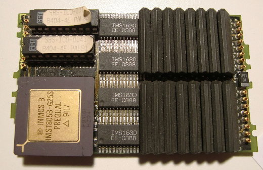
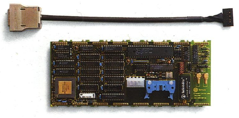
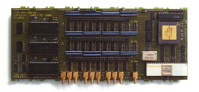
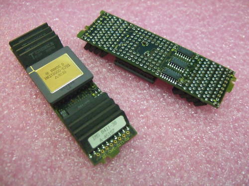
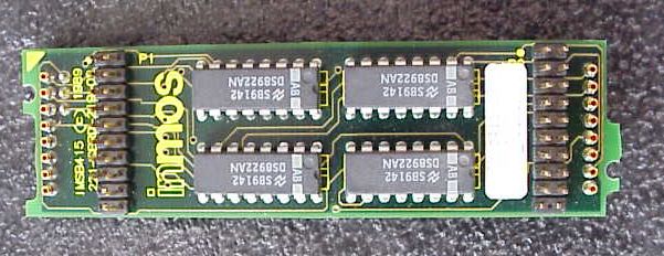
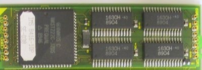
INMOS was obviously the first manufacturer of TRAMs. Over the time you can clearly see the progress the technology made over the period Inmos TRAMs were made. Starting with comparably big sizes, using DIP chips etc. the last of its breed were highly integrated PCBs cramped with SMD parts and chips.
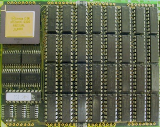
The IMS B401 started it all. A 32KB SRAM size-1 TRAM for a 32-bit Transputer. Here’s the prototype, the final product and a picture of its schematic:

B401_Layout

The “huge” IMS B403 1Mbyte DRAM Size-4 TRAM:

IMSB403_1

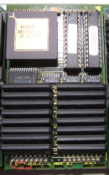
The IMS B404 (2MB DRAM, Size-2) is where the fun starts. Size-2 is just OK not to totally hog your mainboard and 2MB is what you need for OCCAM or HELIOS to make something useful.
Actually, the B404 has 3 “levels” of RAM. 4K internally in the Transputer, 32K SRAM and 2048K DRAM. As they are superimposed (i.e. overlapping), the total amount is still 2MB with different access speed at 0-4k (1 cycle), 5-32k (3 cycles) and 4-5 cycles above.

IMSB404

There were also the IMSB402 (8Kbyte Size-1) and the IMSB405 8Mbyte Size-8 TRAMs of which I have no pictures yet.

The IMS B407 was an Ethernet TRAM (Size-8!), proving that a TRAM doesn’t need to be necessarily a Transputer Module for number crunching only.

imsb407

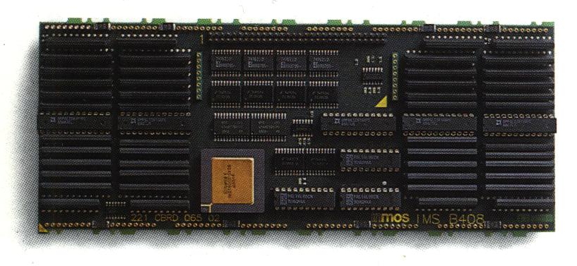
The IMS B408 and B409 were both part of a graphics system, so you didn’t the to have the host to render the graphics – which would have been much slower than those TRAMs.
The B408 was the “drawing pad image storage” (1,25MB dual-ported RAM), while the B409 had the timing generator and the CLUTs:

imsb408

imsb409

The IMS B411 can be seen as a new era: 1MB DRAM on just a size-1 TRAM made possible by the use of small ZIP-packaged DRAMs… which were very expensive, of course.

IMSB411-3B

The IMS B415 is a simple Transputer-Link to RS422 converter. This way, link connections can span up to 30 meters.

imsb415

The IMS B416 features a 16bit T2xx Transputer and 64KB SRAM

IMSB416_10P

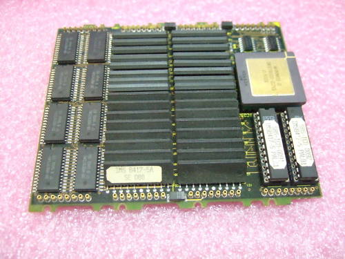
The IMS B417 is a massive beast: 4MB on a size-4 TRAM… well, still better than the B403.

IMSB417-5A

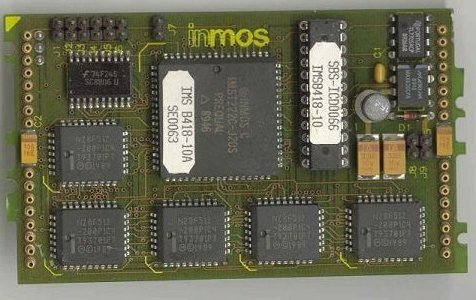
The IMS B418 contains a 16-bit T222 and 256KB Flash ROM… quite modern stuff those days and probably a good way to boot your HELIOS system from 😉

IMSB418_1

The IMS B419 combined the two huge B408 and B409 modules into one size-6 TRAM. A nice graphics TRAM with 2MB DRAM and 2MB VRAM…

imsb419

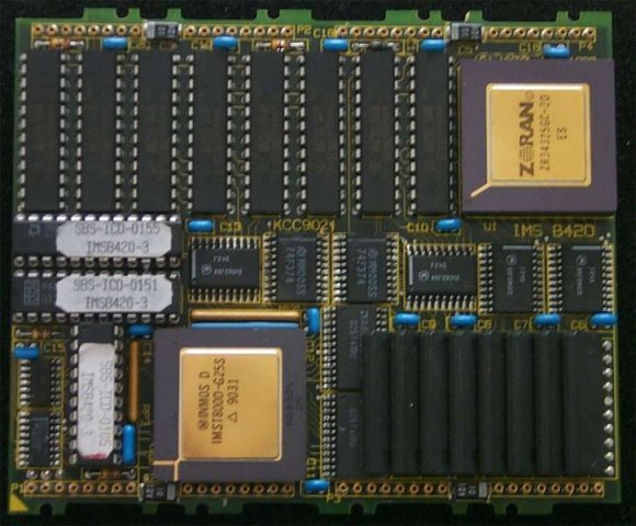
The IMS B420 featured a ZORAN ZR34325 DSP (45 MFLOPS peak) with its own 256KB SRAM besides the obvious T800 Transputer and 4MB DRAM. My guess is, that it is comparable to the Quintek QVA-T TRAM.

imsb420_1

The IMS B421 enabled a Transputer system to talk to GPI/IEEE-488 buses … like laboratory equipment or your old Commodore Floppydrive 😉

IMSB421_1

Ahh, the real-deal… the IMS B426 is what you want in your TRAM collection. 4MB RAM on a size-1 TRAM. This is where Helios really loves to run on.

IMSB426-5A

…and here’s a more recent version of the B426 (rev “-16C”, 1993), this time all SMD, featuring the latest T800 in a nice TQFP case

IMS_B426

Well, the IMS B426 is great… as long as you can’t get the IMS B427 😉 This Size-2 TRAM features a whopping 8MB RAM. Enough for running Helios and X11 on it.

IMSB427

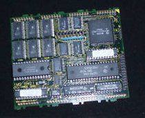
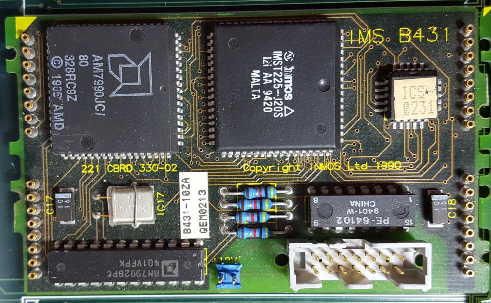
Something more important than ever is a fast network connection. The last ethernet TRAM from INMOS was the IMS B431.
10mbps is the maximum you get… well, more wouldn’t make sense given the Linkspeed of 20mbps.

IMSB431

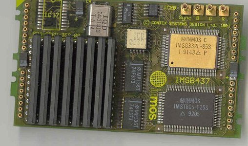
The IMS B437 is a very neat little thing: A graphics TRAM as size-2 TRAM! A nice 25MHz SMD T805 and a G332 colo(u)r video controller. Rare as chicken teeth!
It looks like this was designed by Contex Systems Design Ltd. and OEM’ed by INMOS.

IMSB437_1

And when you thought you’ve seen them all, another one pops up:
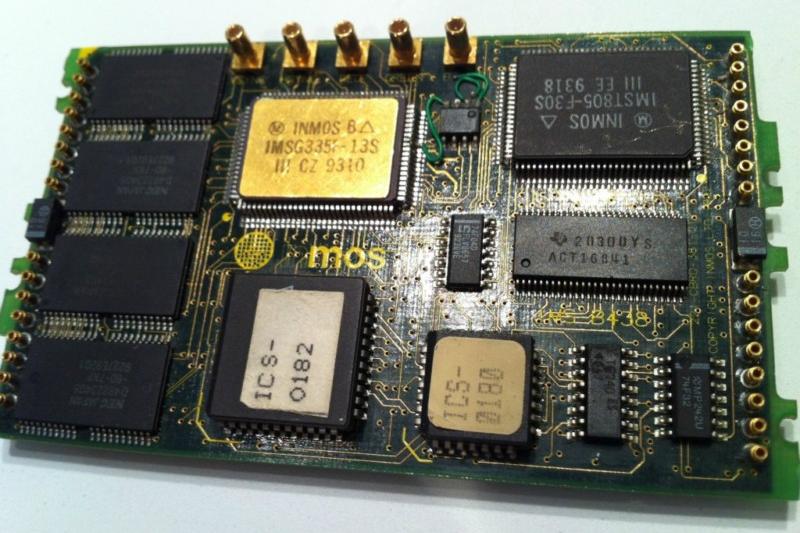
The mighty IMS B438. As the name-code suggests, it’s an updated B437 – very updated and IMHO the ultimate graphics TRAM: 2MB VRAM, 4MB DRAM, 30MHz T805 and the last and final 32Bit video controller G335@130MHz. I really, really want one. Badly!

B438

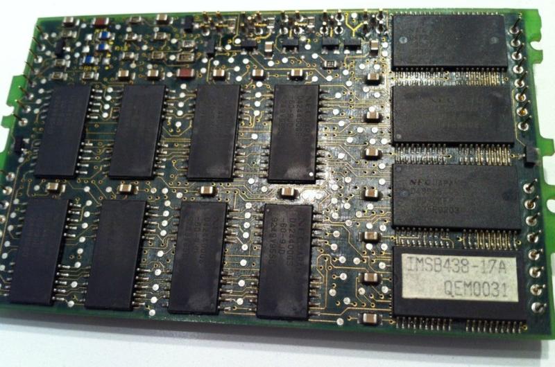
Because it’s a beauty, here’s its back, too:

B438_back

The T9000

Again, Geekdot.com might be the only place left in the World Wide Web where you can get more information about the flopped mysterious T9000 than what you will find on Wikipedia.

The T9000 never made it into the market in higher volumes. I don’t have any numbers on how many T9000 were actually produced but only a few were evaluated outside INMOS by universities and science facilities, most famous is probably the CERN, which did some benchmarks and tests. Here’s a (now funny) promotion video of those days:

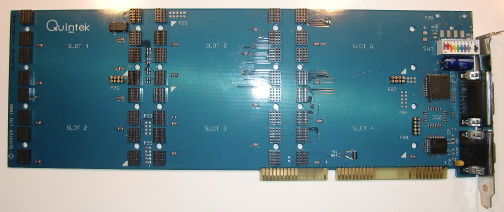
By another lucky incident I got myself a HTRAM mainboard for Christmas 2011. It’s the QT9M from Quintek, a spin-off of INMOS back then. Three slots of this 6-slot board were populated, one featuring the mythical T9000!

This is the naked board, the QT9M:

QT9M_total

At the first look you can see it’s a damn huge thing. At least one inch taller than the slot-backplate. But this way Quintek could squeeze 6 size-1 HTRAM slots (3×2 slots, horizontally) onto the card, while the “official” INMOS B108 (PDF) board just features 2 slots (but size-4, vertically).

The HTRAM slots in detail

(-> For a complete description of HTRAM visit this chapter of geekdot.com)

Not all slots are offering the same features, though. Slot-0, slot 3 (the two middle ones) and slot-2 (lower left) offer the standard pin-blocks 1 and 2 as well as block 3 and 4.
slot-1 (top-left) offers the same pin-blocks but also a small 4×2 horizontally aligned block on its lower edge.
The same 4×2 pin-block can be found on HTRAM-slot 5 (upper right), but this time only the standard pin-blocks 3 and 4 are featured.
Finally, on slot-4 (lower right) only the standard pin-blocks 3 and 4 are featured, too, but it also has a 5×2 pin-block centred to the opposing edge of the standard pin-blocks.
My assumption is that pin-blocks 3 & 4 offer a direct connection into the T9000 memory map, so I’d call slot-4 & 5 “mem-mapped-ony slots”.

The interface logic

The interface logic on the board was kept surprisingly simple. Especially when you compare it to the already mentioned IMS B108, which had an FPGA and two C101 protocol converters.
Without any C101 you can be assure that there won’t be any downward compatible communication as we are used to with the T4xx/T8xx Transputers (OS-Link), so this will be a hard nut to crack :-/

Let’s have a closer look at the “logic side of things”:

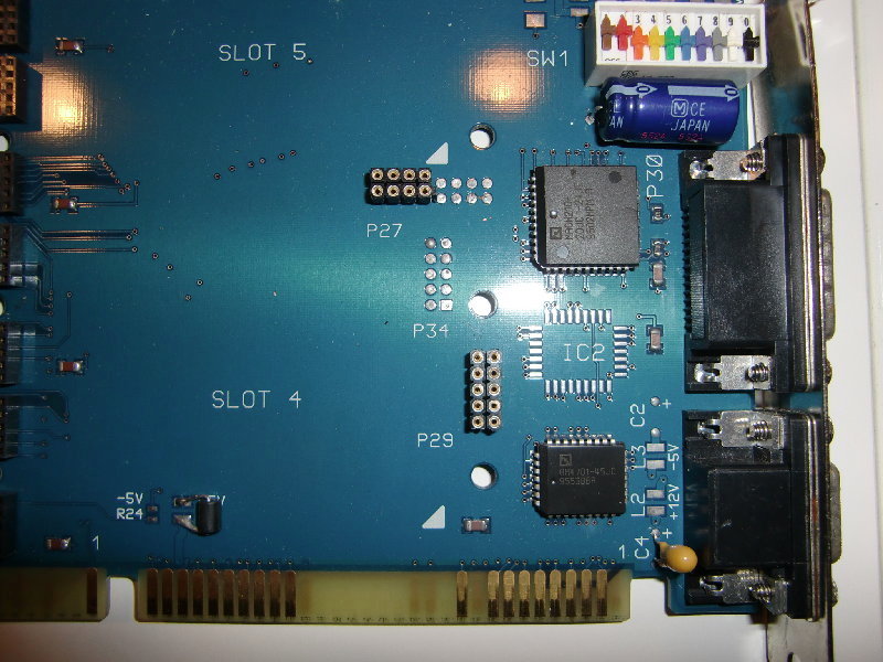
QT9M_detail

There are only 2 ICs: An AMD MACH 210 CPLD and an AMD 4701, which is an 8-bit bi-directional 512 byte deep FiFo Buffer and parity-generator. Given the fact that there’s a place left for IC2, I assume a 2nd 4701 could go there to make the interface 16bit wide (as all 16 ISA data-lines are connected on the slot-connector).

This leads to my totally uneducated guesses, that:

  • The DS data-links are directly connected (through the FiFo) to the ISA bus
  • The control registers of the AM7401 needs to be set – if the default state is not sufficient

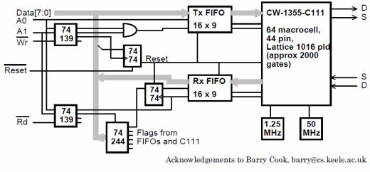
Quite a solid foundation to those assumptions is the following schematic I was able to dig out of the depth of the internet describing an IEEE 1355 interface. IEEE 1355 is the standard which was created out of INMOS’ DS-Links.

DS-Link_CPLD

Everything else…

The function of the colourful DIP-Switch is yet completely unknown. It’s clear that some of these switches will set the base-address for communication with the ISA bus.
The sense behind the two Sub-D connectors at the cards backplate are unknown, too. Maybe some link-outs?

(To be continued…)