Well, normally I wouldn’t list Inmos’ expansion cards here, as they’re normally just TRAM carrier boards and very well documented at the usual places… but for this card, it’s different.
Not only that there isn’t any documentation of the IMSB020 (just a brochure over at Rams page) but this specific card is an updated version of that described in the brochure… I’d call it Rev.2.
It has a T805 instead of a T4xx and probably some more additions…
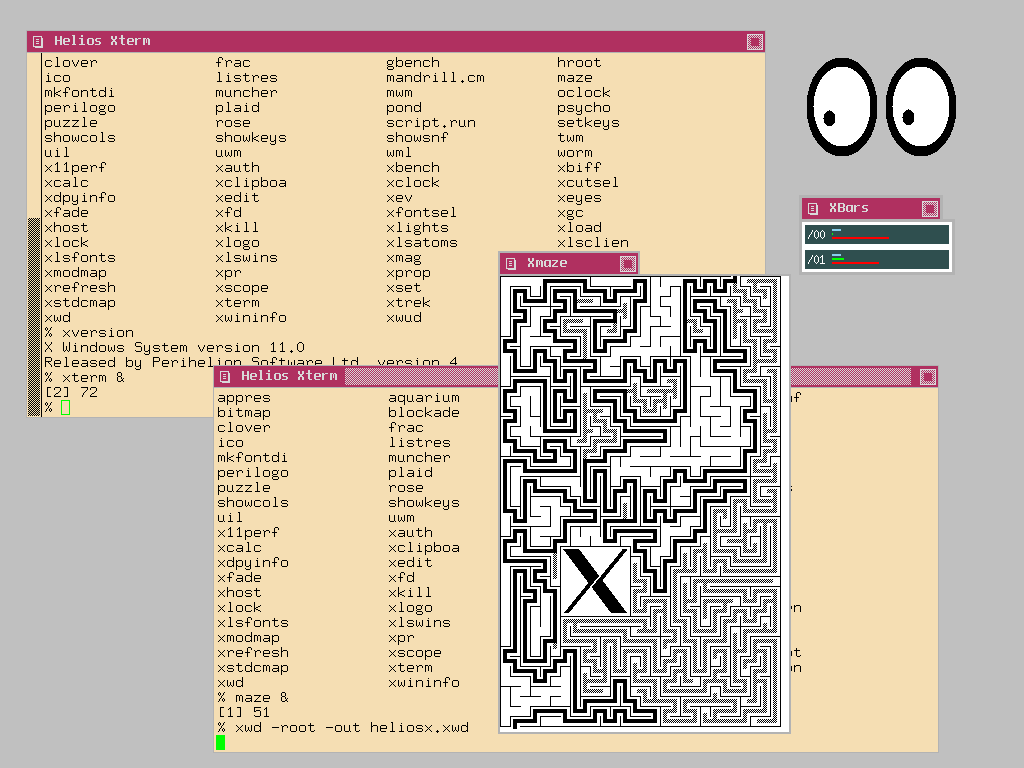
Ok, first of all: What is the Inmos B020 anyway? It’s being sold as a “X11 server on a card”… I’m intentionally writing ‘being sold’ because that just one way of usage.
More generally spoken, it’s an ISA card with a Transputer (with 4-12MB RAM) and a graphics controller on it, an Inmos G332 to be precise. That Transputer controls the G322 and can therefore create graphics onto a VGA screen connected to the board.
- As an avid reader of GeekDot, this should sound familiar to you because it was the typical 90’s approach of High-End Graphics… see the MiroTiger or the SPEA i860 boards.
With the right software being booted into the Transputer, it may act as a X11 (R4) Server… but it could also used as a native Transputer system, e.g. running Helios or some OCCAM code and still create graphics with the G332 controller. As a nice add-on, the card features two size-2 TRAM slots, so more transputers or devices could be added into the equation.
Ah -and as a side note- most people called the B020 “the BOZO“… not very kind but it gets a credit for its pre-l33tc0de usage.
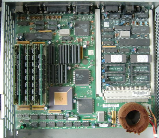
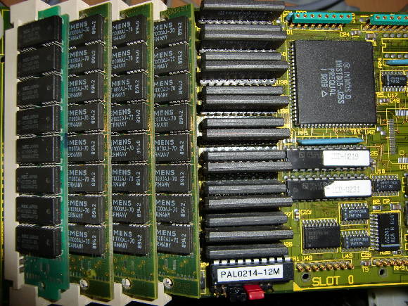
This is how my ‘rev.2’ looks in it’s full glory:
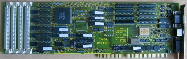
As usual, we go into more detail looking at each half of the card.In this full-view, you can identify the two TRAM-slots by the yellow markings at the lower edge of the card saying “SLOT 0” and “SLOT 1”.
So let’s start with the right half of the B020:
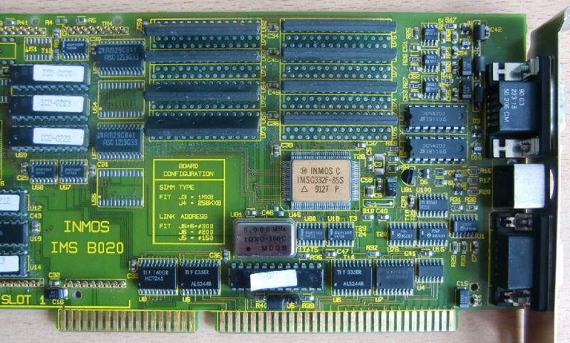
At the right-most edge, there’s the VGA-in and VGA-out connector, so that you can loop-through the video signal from your regular graphics-cards (a fancy ET4000 for example ;-)).
Between the two VGA connectors is an 8-pin Mini-DIN connector, which has this pinout:
1 Error/ (in)
2 Analyse (out)
3 Tram2 Link 2 out
4 Ground
5 Tram2 Link 2 in
6 Onboard T800 link1 out
7 Reset (out)
8 Onboard T800 link 1 in
The upper 2/3, starting with the golden IC (IMSG322F-85F) is all graphics part. Which consists of the G322 controller, 1MB VRAMabove him and some latches and 3 PALs on the left of it.
Below the G322, next to the slot-connector is the ISA interface. That’s handled by a PAL (with the sticker peeling off) and 4 buffers/transceivers and a bit more “chicken food” around them.
Of course there’s also the inevitable 5MHz oscillator which is needed in every Transputer household.
Let’s move to the left half of the card:
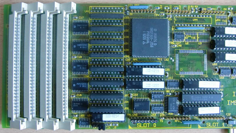
This is ‘where the music plays’. At the lower edge of the right side you can spot the C012 guarded by two PALs (with white labels) who handles the ‘Bus data-to-Transputer’ translation. The two PALs are most likely the subsystem (i.e. handling Reset, Error, the 012’s RS0/1 registers etc.).
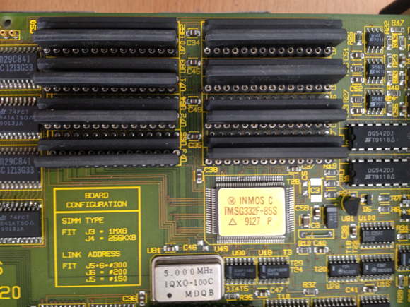
Then there is the King of the Hill, the Transputer himself – a T805-25 in a quite rare PLCC packaging. To his left are 4MB of RAM in ZIP-packaging, most likely configured and controlled by the two PALs below him.
Finally, there are 4 SIMM slots to expand the Transputer memory further to a whopping 8MB! As you can easily see, there are unpopulated solder-pads between the ZIP-RAM ICs (as well as the VRAMs). My assumption is that you could order this card with 8MB soldered, which lead to a max. RAM of 12MB, like mentioned in the brochure on Rams page. But I fear the PALs of the RAM-subsystem need to be programmed accordingly to support the larger amount of RAM (added later: And boy was I right!).
So much for the theory of the B020… and it might stay so for some time, because my B020 is was broken 🙁
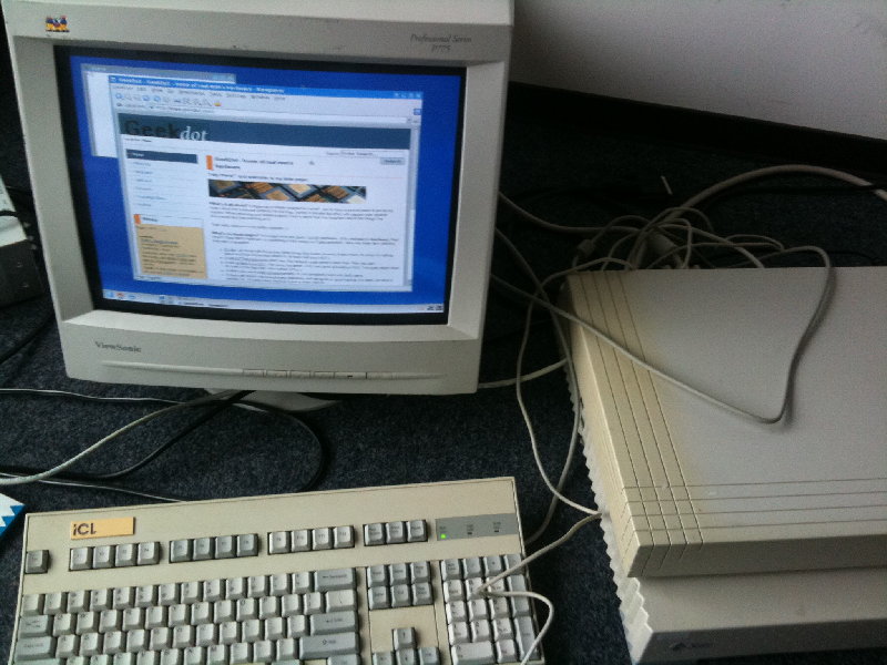
But I’m working on it and one fine day you will see an X11 server in an XT-PC at blazing speed 🙂
Resurrection
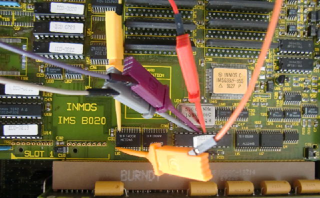
[Nearly 4 weeks later…] As promised, I worked hard on getting the BOZO back to life. It started with weeks of tracing connections of the complete bus-interface, ie. ISA-Bus to the buffers/transceivers, the PAL next to the ISA-bus, the C012 link-adapter etc.etc…
Then, knowing the signals now, came days of staring at the logic analyser, many many mails with Mike Brüstle and lots of hacking with DOSes debug.exe.
Finally it became clear that the PAL 0211 was somehow “confused” and therefore not controlling the bus as it should do. Because there’s no documentation neither of the B020 nor of its PAL equations (like there is for e.g. the B008) I had to go the long and bitter route of reverse-engineering.
So first thing is to remove the faulty part which proved to by a bit tricky – which is a short story of its own available in the DIY-section of this page.
So in went a proper socket and a copy of the original PAL (now a “modern” GAL). The copy proved to be a 100% one… which means not working as it should. But somewhat different than the tries I did before…it was erratic. For example only on I/O port 0x200 I was able to get something useful out of the signals (eg. a well timed /OE for the ‘244 buffers) while jumpering the IO range to 0x150 or 0x300 gave total silence. So I went one step closer to the bus, listening to what the PAL gets on its A4-A11 lines.
There you go! A4-A6 were constantly high and A7 glitching while A8-A11 was happily bouncing. According to my tracing A4-A7 were handled by a different ‘244 than those working. So Sauron turned his eye on the little SMD octal buffers… out went the solder iron and all pins of all buffers were re-soldered.
Lo and behold, the next ispy run on 0x200 worked! Heureka!
Next up: Why is it working on port 0x200 only? Learning from the ‘244 issue I checked all solder-pads concerning the jumper for port 0x150 (that’s J5). Everyhing looked nice and re-soldering didn’t change a bit. So it was the PAL who was suspicious… again.
Luckily INMOS refrained from setting the protection fuse on the PAL, so not only I was able to copy it but also the read its programming. I was thinking about recoding the whole thing and started doing so when I stumbled across a missing “.oe” (Output Enable) for exactly that input-pin connceted to the J5 jumper. So quickly adding
/f14 = gnd
f14.oe = gnd
to the code, compile, burn, plug it into the socket. Tadaa! The B020 now also talks to 0x150… and 0x300 respectively.
[BTW: This happened right at the 30th birthday of DOS. Don’t know if it’s a good or bad sign… at least DOS is my favourite debugging tool 😉 ]
For those who happen to have the same issues with their B020 (erm, that’s probably 1-2 people on this planet by now), here’s my documentation and .jed file for the “PAL 0211B”.
Enhancement
Well, as said in Axels 10 commandments: “Thou should not leave a socket unpopulated!”
And my B020 has a lot of ’em. So I started with the Transputer RAM.
In preparation I checked if the empty solderpads (as you can see in the above pictures) do get all the required signals… well, kind of: I was lazy and just checked /OE with my logic analyser and there was a signal in sync with the one of the already installed RAM. Also all Data- and Addresslines were connected… so it was worth a try!
But I should have known it before: After clearing all 160 pin-holes from the solder, puting self-made zig-zag sockets in place and filling them with the appropriate 1Mx4 RAM chips ispy/mtest still reported just 4MB of RAM :-/
Obviously PAL0214, sitting right below the ZIP RAM was playing an important role here. So the good old routine of “buzzing it through” began. After 2 days I pretty much figured out the purpose of each pin of PAL0214. Yes, it must be the RAM decoder.
So there was no way around removing, reading and replacing it… like with PAL0211.
This time I got myself a desolder-gun – a hell of a facilitation! Again, luckily the PAL wasn’t protected so reading it wasn’t an issue.
As expected, the decoding for the 2nd RAM bank was missing – no idea where the initial measured /OE signals came from.
After the decoding of 1st 4MB ZIP RAM the SIMM RAM followed immediately – so I had to squeeze in the 2nd bank of 4MB ZIP RAM and let the SIMM RAM follow after that. Even my VHDL/PAL Equation skills are quite limited it wasn’t as hard as I expected. Compile, program, put the new GAL16V8 in place, start ispy/mtest, cross fingers….
Using 150 ispy 3.23 | mtest 3.22
# Part rate Link# [ Link0 Link1 Link2 Link3 ] RAM,cycle
0 T805d-25 340k 0 [ HOST ... ... ... ] 4K,1 12284K,4;
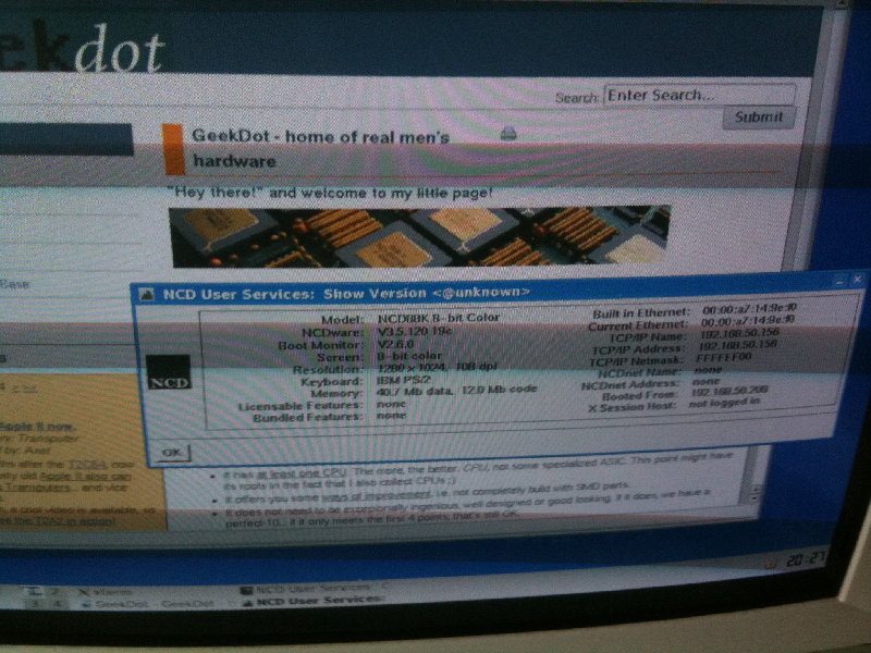
Yay! 12MB including the SIMM RAM!! Here’s the view of a “BOZO to the MAX” 😉
Double the VRAM!
The last step in bringing the BOZO “to the max” was adding more VRAM, i.e. 2MB.
So first you have to get two more AM29C841 9-bit latches (or compatible parts, like those 74FCT841 I’ve used) in SO-24 package. That SMD package is still quite easy to solder onto the board. Here’s a before-and-after picture:
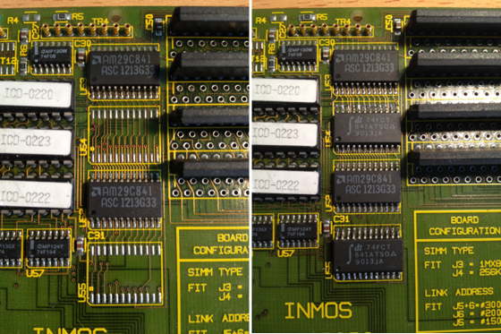
On the right-hand side of the latches you can already spot the empty solder-holes for the VRAM. Like with the DRAM expansion before, I made my own sockets by using two 1×14 pin sockets. This is what the now fully populated VRAM section looks afterwards:
The first run using “ixcheck” from the INMOS iX package went without errors and the /OE signals of all the ‘841s are driven correctly according to my logic analyzer. I was a bit scared that INMOS might have again not completely programmed the PALs (left to the latches) to support this memory expansion but it seems I’ve been lucky.
Next up: Find a tool using the 2MB and confirming that the extra VRAM is actually usable.