Tag Archives: C004

The Cube

Meet The Cube – this is the Transputer Power-House successor to the Tower of Power, which was a bit of a hacked frame-case and based on somewhat non-standard TRAM carriers with a max. capacity of just 24 size-1 TRAMs…

The Cube hardware

This time I went for something slightly bigger  😎 …A clear bow towards the Parsytec GigaCube within a GigaCluster.
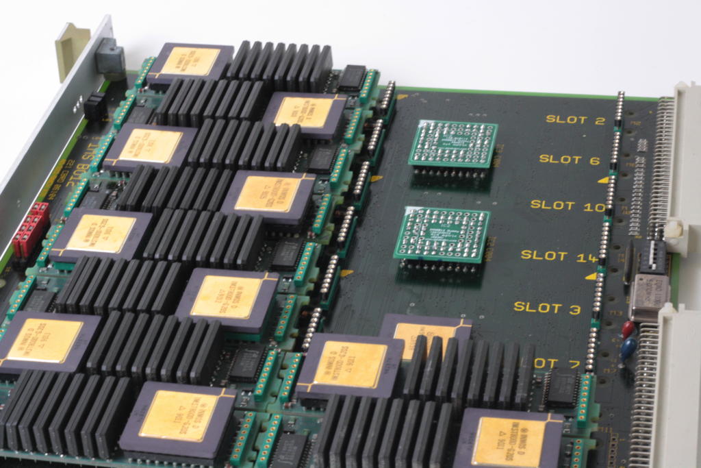
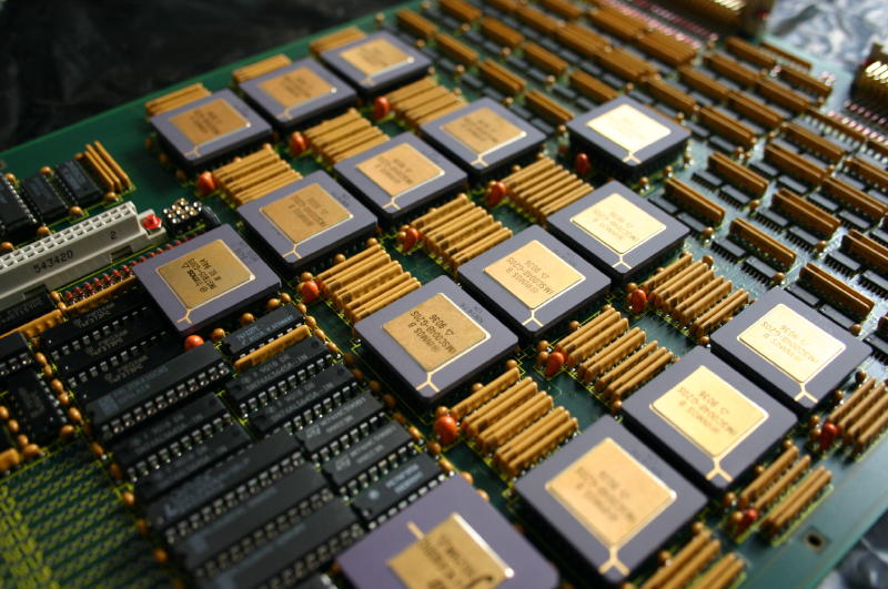
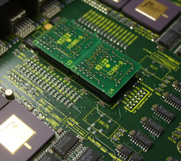
The Cube uses genuine INMOS B012 double-hight Euro-card carriers, giving home to 16 size-1 TRAMs – Parsytec would call this a cluster and so will I.
Currently The Cube uses 4 clusters, making a perfect cube of 4x4x4 Transputers… 64 in total. Wooo-hooo, this seems to be the biggest Transputer network running on this planet (to my knowledge)
If not, there still room left for more  😯

Just to give you a quick preview, this is what ispy responds when ran against the Cube:

Using 150 ispy 3.23 | mtest 3.22  # Part rate Link# [ Link0 Link1 Link2 Link3 ] RAM,cycle  0 T800d-24 276k 0 [ HOST ... ... 1:1 ] 4K,1 1024K,3; Display all 64 lines
1 T800d-25 1.7M 1 [ ... 0:3 2:1 3:0 ] 4K,1 2048K,3; 2 T800d-24 1.8M 1 [ ... 1:2 4:1 5:0 ] 4K,1 2048K,3; 3 T800d-25 1.8M 0 [ 1:3 6:2 5:1 7:0 ] 4K,1 2048K,3; 4 T800d-24 1.8M 1 [ ... 2:2 6:1 8:0 ] 4K,1 2048K,3; 5 T800d-25 1.8M 0 [ 2:3 3:2 8:1 9:0 ] 4K,1 2048K,3; 6 T800d-24 1.8M 2 [ ... 4:2 3:1 10:0 ] 4K,1 2048K,3; 7 T800d-24 1.8M 0 [ 3:3 10:2 9:1 11:0 ] 4K,1 2048K,3; 8 T800d-25 1.8M 0 [ 4:3 5:2 10:1 12:0 ] 4K,1 2048K,3; 9 T800d-25 1.8M 0 [ 5:3 7:2 12:1 13:0 ] 4K,1 2048K,3; 10 T800d-24 1.8M 0 [ 6:3 8:2 7:1 14:0 ] 4K,1 2048K,3; 11 T800d-24 1.8M 0 [ 7:3 14:2 13:1 15:0 ] 4K,1 2048K,3; 12 T800d-25 1.8M 0 [ 8:3 9:2 14:1 16:0 ] 4K,1 2048K,3; 13 T800d-25 1.8M 0 [ 9:3 11:2 16:1 17:0 ] 4K,1 2048K,3; 14 T800d-24 1.8M 0 [ 10:3 12:2 11:1 18:0 ] 4K,1 2048K,3; 15 T800d-25 1.8M 0 [ 11:3 ... 17:1 19:0 ] 4K,1 2048K,3; 16 T800d-24 1.8M 0 [ 12:3 13:2 18:1 20:0 ] 4K,1 2048K,3; 17 T800d-25 1.8M 0 [ 13:3 15:2 20:1 21:0 ] 4K,1 2048K,3; 18 T800d-25 1.8M 0 [ 14:3 16:2 ... 22:0 ] 4K,1 2048K,3; 19 T800d-25 1.8M 0 [ 15:3 22:2 21:1 23:0 ] 4K,1 2048K,3; 20 T800d-25 1.8M 0 [ 16:3 17:2 22:1 24:0 ] 4K,1 2048K,3; 21 T800d-25 1.8M 0 [ 17:3 19:2 24:1 25:0 ] 4K,1 2048K,3; 22 T800d-25 1.8M 0 [ 18:3 20:2 19:1 26:0 ] 4K,1 2048K,3; 23 T800d-25 1.8M 0 [ 19:3 26:2 25:1 27:0 ] 4K,1 2048K,3; 24 T800d-24 1.8M 0 [ 20:3 21:2 26:1 28:0 ] 4K,1 2048K,3; 25 T800d-25 1.8M 0 [ 21:3 23:2 28:1 29:0 ] 4K,1 2048K,3; 26 T800d-25 1.7M 0 [ 22:3 24:2 23:1 30:0 ] 4K,1 2048K,3; 27 T800d-24 1.8M 0 [ 23:3 30:2 29:1 31:0 ] 4K,1 2048K,3; 28 T800d-25 1.8M 0 [ 24:3 25:2 30:1 32:0 ] 4K,1 2048K,3; 29 T800d-25 1.8M 0 [ 25:3 27:2 32:1 33:0 ] 4K,1 2048K,3; 30 T800d-25 1.8M 0 [ 26:3 28:2 27:1 34:0 ] 4K,1 2048K,3; 31 T805d-20 1.7M 0 [ 27:3 ... 33:1 35:0 ] 4K,1 1024K,3; 32 T800d-24 1.8M 0 [ 28:3 29:2 34:1 36:0 ] 4K,1 2048K,3; 33 T800d-20 1.8M 0 [ 29:3 31:2 36:1 37:0 ] 4K,1 1024K,3; 34 T800d-24 1.8M 0 [ 30:3 32:2 ... 38:0 ] 4K,1 2048K,3; 35 T800c-20 1.8M 0 [ 31:3 38:2 37:1 39:0 ] 4K,1 1024K,3; 36 T805d-20 1.7M 0 [ 32:3 33:2 38:1 40:0 ] 4K,1 1024K,3; 37 T800c-20 1.6M 0 [ 33:3 35:2 40:1 41:0 ] 4K,1 1024K,3; 38 T800d-20 1.6M 0 [ 34:3 36:2 35:1 42:0 ] 4K,1 1024K,3; 39 T800d-20 1.7M 0 [ 35:3 42:2 41:1 43:0 ] 4K,1 1024K,3; 40 T800d-20 1.8M 0 [ 36:3 37:2 42:1 44:0 ] 4K,1 1024K,3; 41 T800d-20 1.7M 0 [ 37:3 39:2 44:1 45:0 ] 4K,1 1024K,3; 42 T800d-20 1.8M 0 [ 38:3 40:2 39:1 46:0 ] 4K,1 1024K,3; 43 T800d-20 1.8M 0 [ 39:3 46:2 45:1 47:0 ] 4K,1 1024K,3; 44 T800d-20 1.8M 0 [ 40:3 41:2 46:1 48:0 ] 4K,1 1024K,3; 45 T800d-20 1.8M 0 [ 41:3 43:2 48:1 49:0 ] 4K,1 1024K,3; 46 T800d-20 1.7M 0 [ 42:3 44:2 43:1 50:0 ] 4K,1 1024K,3; 47 T800d-20 1.8M 0 [ 43:3 ... 49:1 51:0 ] 4K,1 1024K,3; 48 T800d-20 1.8M 0 [ 44:3 45:2 50:1 52:0 ] 4K,1 1024K,3; 49 T800d-20 1.6M 0 [ 45:3 47:2 52:1 53:0 ] 4K,1 1024K,3; 50 T800d-20 1.8M 0 [ 46:3 48:2 ... 54:0 ] 4K,1 1024K,3; 51 T800d-20 1.8M 0 [ 47:3 54:2 53:1 55:0 ] 4K,1 1024K,3; 52 T800d-20 1.8M 0 [ 48:3 49:2 54:1 56:0 ] 4K,1 1024K,3; 53 T800d-20 1.8M 0 [ 49:3 51:2 56:1 57:0 ] 4K,1 1024K,3; 54 T800d-20 1.6M 0 [ 50:3 52:2 51:1 58:0 ] 4K,1 1024K,3; 55 T800d-20 1.8M 0 [ 51:3 58:2 57:1 59:0 ] 4K,1 1024K,3; 56 T800d-20 1.7M 0 [ 52:3 53:2 58:1 60:0 ] 4K,1 1024K,3; 57 T800d-20 1.8M 0 [ 53:3 55:2 60:1 61:0 ] 4K,1 1024K,3; 58 T800d-20 1.8M 0 [ 54:3 56:2 55:1 62:0 ] 4K,1 1024K,3; 59 T800d-20 1.8M 0 [ 55:3 ... 61:1 ... ] 4K,1 1024K,3; 60 T800d-20 1.7M 0 [ 56:3 57:2 62:1 63:0 ] 4K,1 1024K,3; 61 T800d-20 1.6M 0 [ 57:3 59:2 63:1 ... ] 4K,1 1024K,3; 62 T800d-20 1.8M 0 [ 58:3 60:2 ... 64:0 ] 4K,1 1024K,3; 63 T800d-20 1.8M 0 [ 60:3 61:2 64:1 ... ] 4K,1 1024K,3; 64 T800d-20 1.7M 0 [ 62:3 63:2 ... ... ] 4K,1 1024K,3;

Here are some more figures:

  • 32 x T800@25Mhz/2MB  (my very own AM-B404 TRAMs)
  • 32 x T800@20MHz/1MB  (mainly TRAMs from MSC and ARADEX)
  • -> 96MB of total RAM
  • -> 70-130 MFLOPS (single precision)
  • ~800MIPS combined integer power
  • ~60Amps @5V needed (That’s 300W  😯 )

So we’re talking about 70-130 MFLOPS here – depending which documentation you trust and what language (OCCAM vs. Fortran) and/or OS you’re using. That was quite a powerhouse back in 1990 (Cray XM-P class!)… and dwarfed by a simple Pentium III some years later 😉
Just for to give you an comparison with recent hardware (Linpack MFlops):

Raspberry Pi Model B+ (700 MHz) ~40 DP Mflops
Raspberry Pi 2 Model B (1000 MHz – one core) ~134 DP Mflops
Raspberry Pi 3 Model B (1200 MHz – one core) ~176 DP Mflops

Short break for contemplation about getting old…

Ok, let’s go on… you want to see it. Here it is – the front, one card/cluster pulled, 3 still in. On the left the mighty ol’ 60A power supply:

Cube_Front_4x

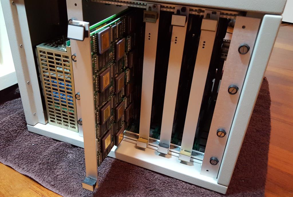
Well, this is the evaluation version in a standard case, i.e. this is meant for testing and improving. I’m planning for a somehow cooler and more stylish case for the final version (read: Blinkenlights etc.).

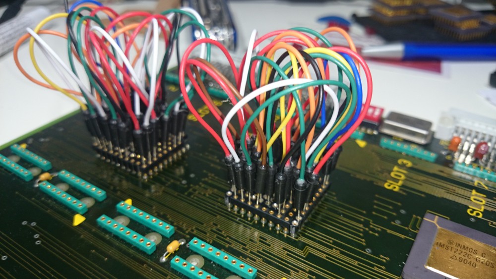
And here’s the IMHO more interesting view… the backside. It shows the typical INMOS cabling.

CubeBack

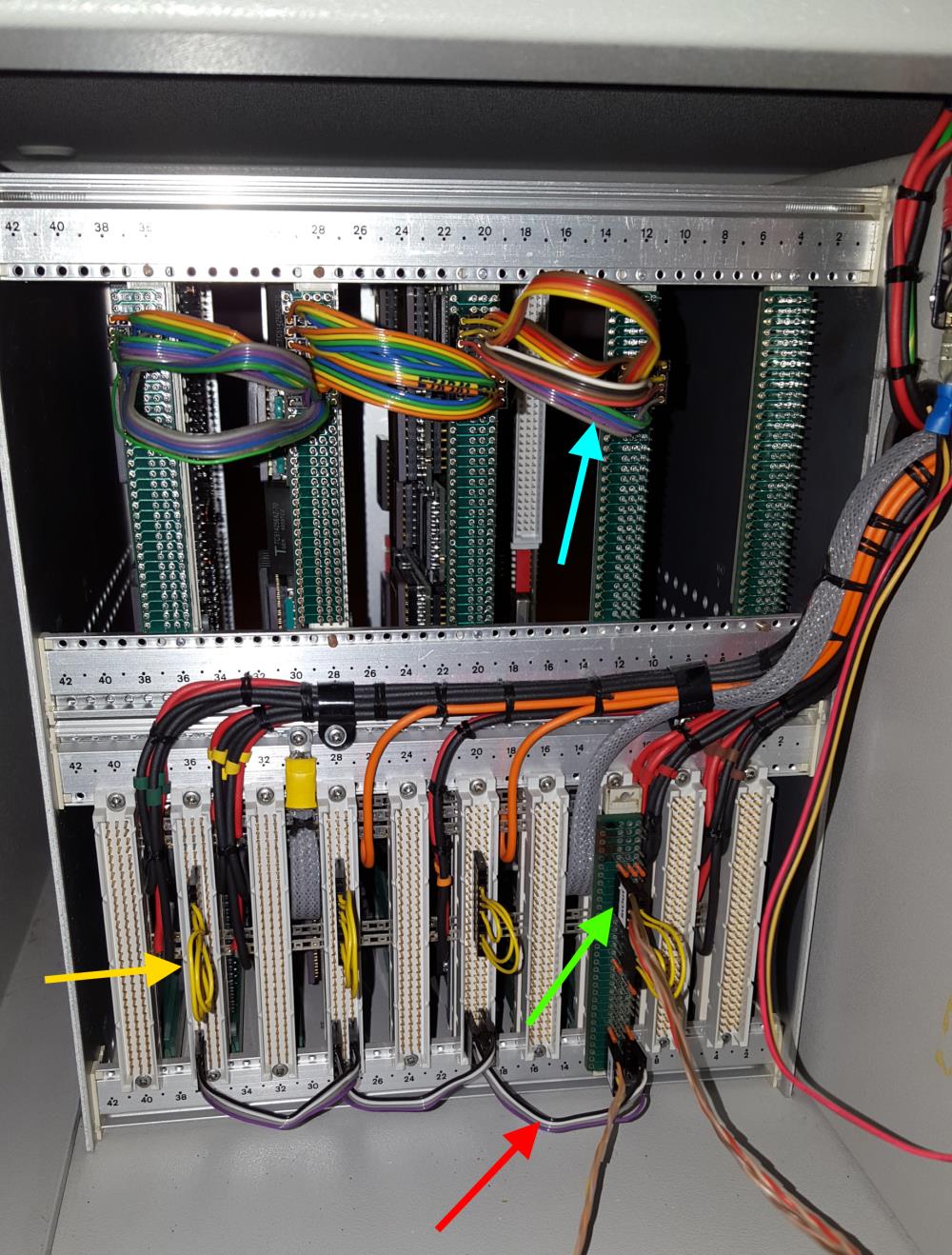
As usual, I color coded some of the cables.
The green arrow points to the uplink to the host system to which The Cube is connected to. Red are the daisy-chained Analyse/Reset/Error (ARE) signals. The yellow so-called jumper-cables connect some of the IMSB004 links back into the boards network. And in the upper row (blue) four ‘edge-links’ of each board are connected to its neighbor.

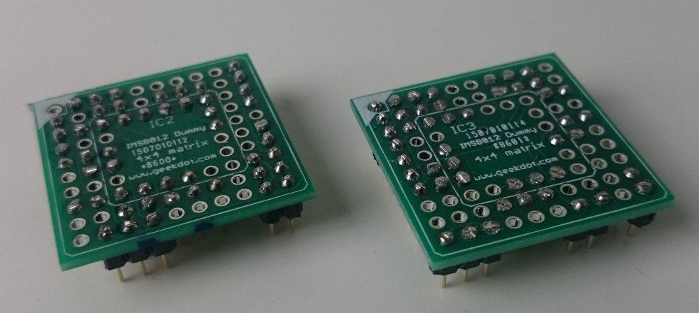
This setup connects four 4×4 matrices (using my C004 dummies as discussed here)  into a big 4×16 matrix. Finally I will ‘wrap’ that matrix into a torus. Yeah, there might be more clever topologies, but for now I’m fine with this.

Building up power

For completeness, here’s a quick look at how things came together.

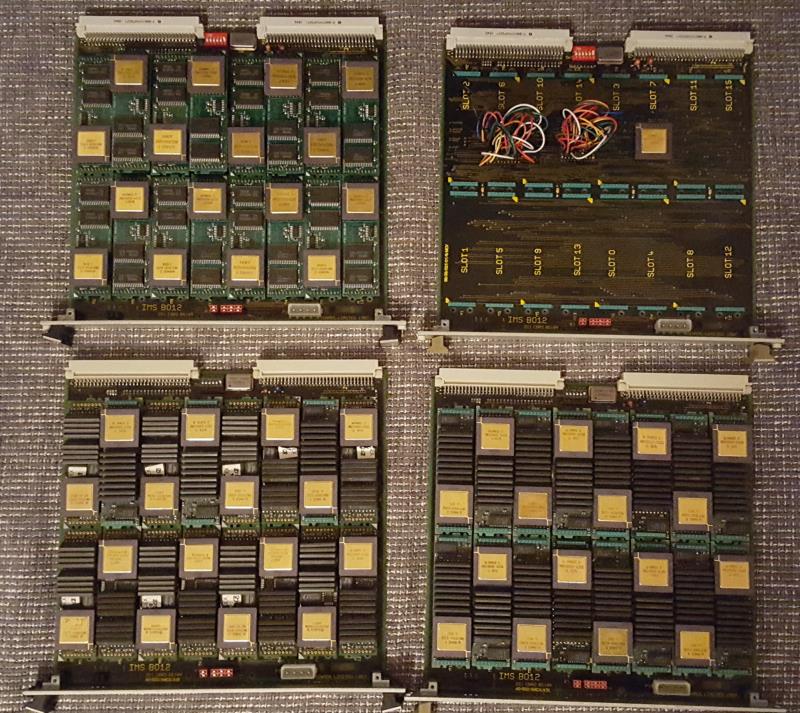
The 4 carriers/clusters with lots of size-1 TRAMs… upper right one is the C004-dummy test board (now also fully populated). Upper left is pure AM-B404 love <3

ITEM_futter

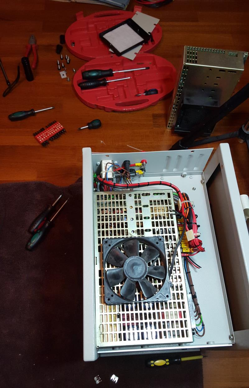
Fixing/replacing the broken power-supply (in the back), including the somewhat difficult search for a working cooling solution:

ITEM_repairing

The Cube software

Well there isn’t any specific software needed to run The Cube, but it definitely cries out loud for some heavily multi-threaded stuff.

So the first thing has definitely to be a Mandelbrot zoom. As usual, I used my very own version with a high-precision timer, available in my Transputer Toolkit.

Here’s the quick run in real-time – you can still figure out visually each Transputer delivering its result:

Other Transputer and x86 results of this benchmark can be seen in this post over here.

We need (even) more power, Igor!

So this is running fine – using internal RAM only. On the other hand, it seems that the current power supply has some issues with, well, the electric current.
When booting Helios onto all 64/65 Transputers which uses all of the external RAM, very soon some of them do crash or go into a constant reboot-loop.
By just reducing the network definition (i.e. not pulling any Transputers) to 48, Helios boots and runs rock-solid.
Because measuring the voltage during a 64-T boot shows a solid 5.08V on all TRAM-slots it most likely means the power supply either can’t deliver the needed amount of Amps (~60) or produces noise etc.  😥
So this is the next construction site I have to tackle.

To be continued…

IMSB012 C004 replacement

The IMSB012 is my favorite TRAM carrier board. Room for max. 16 (size-1) TRAMs and plenty of external connectors. The perfect platform to build a successor of the ‘Tower of Power’.

Like with all TRAM carriers having more than 8 slots, it was a good decision to put at least one C004 link-switch onto the board.
While that’s generally a good feature, you (and me) might not need the option to reconfigure your Transputer network several times a week… And if you’re completely sure how you like your network it would be better to set if once and for all without the signal delay penalty you have to pay using one or even two C004s.

So in my case, I’m perfectly fine with the 4×4 matrix mentioned in the B012 manual (and also used as an example in my C004 post). So instead of using the clumsy MMS tool and having an extra link used into the T212, I planned tp remove the T212 and the two C004s and replace them with two dummies. Pretty much the same way like Parsytec did it with their x’plorer.
First I had to chew myself through the B012 schematic to understand the connection of each TRAM slot into the C004s. After that it was time for some intense cable plugging:

C004 dummy test

If you plan to do so, please be aware that the socket holes are too thin for a normal (0.63mm?) jumper cable. You might ruin your socket if you use force to plug them in!
I created a interpose socket by using single row pin header sockets which itself had thin enough pins to fit into the original B012 socket.

After some corrections, the buzzing-through of all 16 slots went fine and the schematics went to the PCB house (I have some PCBs left, ask for a quote if you need some).

And this is how the C004 replacement PCBs look when completed:

IMSB012 C004 dummies

Again, to solder in the pins, you’ll need really thin ones. Thinner than 0.5mm that is. Also, you don’t need to populate all 84 pins, I only use 51 per dummy (bridging some gaps).

Additionally, I strongly advise to isolate each dummy’s top with some kind of tape to avoid (electrical) contact to the TRAM placed above it. This is how they look seated on the B012 underneath slot 6 and 14 – the T212 under slot 7 not yet removed:

in_IMSB012

The Inmos C004

Hardware

Before I reinvent the wheel, here’s the quick intro from the manual, what an Inmos C004 actually is:

The IMS C004 is a transparent programmable link switch designed to provide a full crossbar switch between 32 link inputs and 32 link outputs. The IMS C004 will switch links running at either the standard speed of 10 Mbits/sec or at the higher speed of 20 Mbits/sec.
It introduces, on average, only a 1.75 bit time delay on the signal. Link switches can be cascaded to any depth without loss of signal integrity and can be used to construct reconfigurable networks of arbitrary size. The switch is programmed via a separate serial link called the configuration link.

So in simple words: 32 inputs can be freely connected to 32 outputs. Great for large Transputer networks which can be reconfigured only by reprogramming the C004 – on top of that, you can cascade them and create huge, complex networks to make any connection imaginable possible. Like those Parsytec used in their SuperCluster machines looking like this:

MegaFrameXbarDetailYes, that’s 13 C004s and one Transputer to rule them all…

… so much for the theory.

In practice, the C004 is a bitch. Not only does it require a Transputer to configure it (normally a 16bit T2xx) it also adds quite a delay into the link-communication. As mentioned above, it’s “only a 1.75 bit time delay” but this can sum up to quite an amount.
Let me quote some more realistic numbers from the Helios manual (pp.255):

It is of interest to ascertain the effect of the Inmos C004 on the performance of the Helios communication mechanisms. Figure 6.3 illustrates the rates of data communication (Kbytes/second) attained using message passing primitives (PutMsg() and GetMsg()) between two Transputers that were
1. Directly linked and
2. Connected through a C004 link switch.
It is evident from Figure 6.3 that the effect of the C004 link switch on the rate of communication is far from negligible. The overhead imposed by the link switch increases with the size of the message. In the worst case (64 Kbyte message), transmission through the C004 is 23 % slower than sending data over directly connected links.

C004_helios

Oops. 23% is quite essential. So before planning to set up a crazy C004 network you might consider what you want to achieve.
Is it for educational network studies only? Fine.
Are you going for speed and rarely change your Transputer network configuration? Avoid it!

IMHO even the 10 possible Transputers on an IMSB008 do not require a C004 making your day.
Actually, even Parsytec thought that this is useless to use a link switch for the 16 Transputers in their beautiful x’plorer and replaced it by hard-wire dummies:

C004_dummies2

Configuration

Ok, you’re still not scared away and really do like to know how to handle that beast. Fine, here’s what I went through:

To work with a C004 you obviously need either a TRAM carrier like the B008 or some sort of motherboard like the IMSB012 or IMSB014.  Read the boards manual to understand how to connect to the T2xx Network Control Processor (NCP).
For example the IMSB012 has extra pins for “config down” (i.e. IN) and “config up” (i.e. OUT) for its T212 and any other boards being chained to it.
As for the IMSB008 has its T222 connected to Link 1 of TRAM 0.

The hardware wiring is important to know, because this information is needed for the so-called hardwire file used by the INMOS tool “MMS2” (Module Motherboard Software, MSDOS only, the manual is available here).
After reading the manual (do!) you should be able to read this hardwire file for an B008 quite easily. It describes the complete hardware setup and all physical connection between the C004(s), T2xx and Transputer/TRAM links on the board:

-- B008 hardwire description
DEF B008
  SIZES
    T2 1
    C4 1
    SLOT 10
    EDGE 10
   END
   T2CHAIN
     T2 0, LINK 3 C4 0
   END
   HARDWIRE
     SLOT 0,LINK 2 TO SLOT 1,LINK 1
     SLOT 1,LINK 2 TO SLOT 2,LINK 1
     SLOT 2,LINK 2 TO SLOT 3,LINK 1
     SLOT 3,LINK 2 TO SLOT 4,LINK 1
     SLOT 4,LINK 2 TO SLOT 5,LINK 1
     SLOT 5,LINK 2 TO SLOT 6,LINK 1
     SLOT 6,LINK 2 TO SLOT 7,LINK 1
     SLOT 7,LINK 2 TO SLOT 8,LINK 1
     SLOT 8,LINK 2 TO SLOT 9,LINK 1
     C4 0,LINK 10 TO SLOT 0,LINK 3
     C4 0,LINK 1 TO SLOT 1,LINK 0
     C4 0,LINK 11 TO SLOT 1,LINK 3
     C4 0,LINK 2 TO SLOT 2,LINK 0
     C4 0,LINK 12 TO SLOT 2,LINK 3
     C4 0,LINK 3 TO SLOT 3,LINK 0
     C4 0,LINK 13 TO SLOT 3,LINK 3
     C4 0,LINK 4 TO SLOT 4,LINK 0
     C4 0,LINK 14 TO SLOT 4,LINK 3
     C4 0,LINK 5 TO SLOT 5,LINK 0
     C4 0,LINK 15 TO SLOT 5,LINK 3
     C4 0,LINK 6 TO SLOT 6,LINK 0
     C4 0,LINK 16 TO SLOT 6,LINK 3
     C4 0,LINK 7 TO SLOT 7,LINK 0
     C4 0,LINK 17 TO SLOT 7,LINK 3
     C4 0,LINK 8 TO SLOT 8,LINK 0
     C4 0,LINK 18 TO SLOT 8,LINK 3
     C4 0,LINK 9 TO SLOT 9,LINK 0
     C4 0,LINK 19 TO SLOT 9,LINK 3
     C4 0,LINK 20 TO EDGE 0
     C4 0,LINK 21 TO EDGE 1
     C4 0,LINK 22 TO EDGE 2
     C4 0,LINK 23 TO EDGE 3
     C4 0,LINK 24 TO EDGE 4
     C4 0,LINK 25 TO EDGE 5
     C4 0,LINK 26 TO EDGE 6
     C4 0,LINK 27 TO EDGE 7
 -- Uncomment the next two lines if the
 -- patch header wiring is used to
 -- connect C004, link 28 to PatchLink0,
 -- and C004, link 29 to PatchLink1.
 -- C4 0,LINK 28 TO EDGE 8
 -- C4 0,LINK 29 TO EDGE 9
   END
PIPE B008 END

After that’s done, you can prepare a second file. The so called “softwire file” which actually tells the T2xx how to internally connect his in- and out-links. A very simple example would be:

SOFTWIRE 
PIPE 0
 SLOT 0,3 TO SLOT 1,3 
END

This would connect TRAM-0’s 3rd link to TRAM-1’s 3rd link.
Now that you have the necessary config files let’s move on to the MMS itself.

Software

As with nearly every software from INMOS the MMS too is written in OCCAM and therefore has to run on a Transputer. This might be the one in TRAM slot 0 on your B008 or on a local ISA board which itself is connected with 2 links to a B012 (one for config and one to the Transputer network).

To make things easier, I prepared a complete MMS archive to download here (links to my Transputer Software page).
It contains some example soft- and hardwire files, an ISERVER.EXE (the program you need to upload code into your Transputer) as well as a batch file to easily start MMS (RUN_MMS.BAT).
Also you will find a folder with INMOS’ pimped version of ANSI.SYS called BANSI (“Better ANSI”), because all INMOS tools make heavy use of ANSI screen control. So put that into your CONFIG.SYS.

Before we begin, let’s have a look at my IMSB012 with ispy:

ispy 2.33
   # Part rate Mb Bt [  Link0  Link1  Link2  Link3 ]
   0 T800d-25 0.37 0 [   HOST    1:1    2:1    ... ]
   1 T2   -20 1.64 1 [    ...    0:1    ...    ... ]
   2 T800d-25 1.75 1 [    ...    0:2    3:1    ... ]
   3 T800d-25 1.77 1 [    ...    2:2    4:1    ... ]
   4 T800d-25 1.77 1 [    ...    3:2    5:1    ... ]
   5 T800d-25 1.75 1 [    ...    4:2    6:1    ... ]
   6 T800d-25 1.75 1 [    ...    5:2    7:1    ... ]
   7 T800d-25 1.75 1 [    ...    6:2    8:1    ... ]
   8 T800d-25 1.75 1 [    ...    7:2    9:1    ... ]
   9 T800d-25 1.75 1 [    ...    8:2   10:1    ... ]
  10 T800d-25 1.75 1 [    ...    9:2   11:1    ... ]
  11 T800d-25 1.75 1 [    ...   10:2   12:1    ... ]
  12 T800d-25 1.75 1 [    ...   11:2   13:1    ... ]
  13 T800d-25 1.77 1 [    ...   12:2   14:1    ... ]
  14 T800d-25 1.77 1 [    ...   13:2   15:1    ... ]
  15 T800d-25 1.75 1 [    ...   14:2   16:1    ... ]
  16 T800d-25 1.77 1 [    ...   15:2   17:1    ... ]
  17 T800d-25 1.77 1 [    ...   16:2    ...    ... ]

Ok, let’s start MMS2. Use/modify the batch “run_mms.bat” which will do all environment variables expected by iserver.exe and also adds the input and output files – change it as you please.
If everything works fine, iserver loads MMS2.B4 onto your Transputer and executes it. Your screen should look like the screenshot below.
First, I suggest you press “c” for checking the consistency of your hard/softwire files – if everything’s fine, MMS2 will print “Source files checked O.K.” as seen in the lowest line in the screenshot.

MMS1

Just for the fun of it, you can try MMS’ very own network worm – so press “n” to start the network mapper. You will see that it is much slower than e.g. ispy, so just be patient.
After some seconds, you should get something like this:

MMS2

Now it’s time to program you network. So press “s” to set the C004(s). Some infos will rush trough the bottom line of the screen and finally MMS2 states “C004 setting preformed O.K.“:

MMS3

Nothing more to do here so press “q” to quit MMS2.  (Do not run the network mapper again! It seems to reset the T2 and in my case reproducibly crashes the network).
It’s better to use ispy. ispy v2.33 to be precise. I encountered several issues with the C004 and the most recent version 3.23 of ispy.

So running ispy including the /C4  switch to display the settings of the two C004s now shows this – mind all the new connections of each Transputers Link0 and 3:

ispy 2.33
   # Part rate Mb Bt [  Link0  Link1  Link2  Link3 ]
   0 T800d-25 0.37 0 [   HOST    1:1    4:1    ... ]
   1 T2   -20 1.74 1 [    2:C    0:1    ...    3:C ]
   2 C004b   [ 6S3JM54V --U8-1C- -G--F9-I T--7-PQ- ]
   3 C004b   [ -D-2650R BL--E--K H-N3--4- -TU-1OA7 ]
   4 T800d-25 1.65 1 [    ...    0:2    5:1    6:0 ]
   5 T800d-25 1.75 1 [    ...    4:2    7:1    8:0 ]
   6 T800d-25 1.41 0 [    4:3    9:2    8:1   10:0 ]
   7 T800d-25 1.75 1 [    ...    5:2    9:1   11:0 ]
   8 T800d-25 1.41 0 [    5:3    6:2   11:1   12:0 ]
   9 T800d-25 1.75 2 [    ...    7:2    6:1   13:0 ]
  10 T800d-25 1.35 0 [    6:3   13:2   12:1   14:0 ]
  11 T800d-25 1.41 0 [    7:3    8:2   13:1   15:0 ]
  12 T800d-25 1.42 0 [    8:3   10:2   15:1   16:0 ]
  13 T800d-25 1.32 0 [    9:3   11:2   10:1   17:0 ]
  14 T800d-25 1.35 0 [   10:3   17:2   16:1    ... ]
  15 T800d-25 1.41 0 [   11:3   12:2   17:1   18:0 ]
  16 T800d-25 1.33 0 [   12:3   14:2   18:1    ... ]
  17 T800d-25 1.32 0 [   13:3   15:2   14:1   19:0 ]
  18 T800d-25 1.35 0 [   15:3   16:2   19:1    ... ]
  19 T800d-25 1.32 0 [   17:3   18:2    ...    ... ]

Yay! It worked. Positively as well as negatively.
Besides the new connections you might also spot a difference in the link-speed column. In our first run of ispy all Transputers had a link-speed around 1.75MBps.  Now it varies between 1.75 and 1.32, depending on how often the ispy worm crossed a C004.

Two final hints:

If your C004 network has been set-up as planned, you can use ispys output to programm the network later.
Just save the output into an ASCII file (ispy /c4 > my_net.txt) and when needed feed it back into ispy like this:
 ispy /r /cr < my_net.txt
This will reset the network and read in the configuration from stdin.
Obviously you can also manually edit the text file, the c4 lines

   2 C004b   [ 6S3JM54V --U8-1C- -G--F9-I T--7-PQ- ]
   3 C004b   [ -D-2650R BL--E--K H-N3--4- -TU-1OA7 ]

which isn’t as comfortable and comprehensible as editing a hard/softwire file. But your mileage my vary.

Alternatively, MMS2 can create a bootable file with your network settings. This can be used for quickly setting-up your system.
Just hit the “b” key and enter a filename. My MMS2 archive contains the above example as “BOOTB012.BTL”. Run it with “iserver /SB bootb012.btl“.

Caveats

Mind your reset! This means, in many cases a root Transputer might reset all the “worker Transputers” but also your T2xx and in effect all C004. So be careful when resetting your system.

Yes, theoretically you can reconfigure your Inmos C004 on the fly while all connected Transputer run. The most prominent example is having one network topology during data acquisition while changing it for number crunching later on.
This requires a very good knowledge of the notwork and thorough process locking etc.