It’s yet unclear how to write its name correctly. Some sources use XPlorer, others xPlorer and many other permutations. As my model has this logo at the front of its case 
I’m going to use x’plorer. Having this burning issue off my chest, let’s go into details 😉
The x’plorer is more or less a single “slice” -Parsytec called them cluster– of a GigaCube, which used 4 of those clusters in its smallest 64-Transputer version (GC-1). Thus, the x’plorer features 16 Transputers, each having access to 4MB RAM in a gorgeousdesktop case. If you want, you could call it a “GC-0.25”. 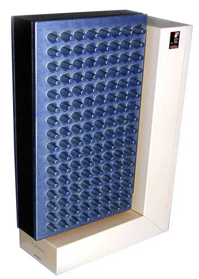
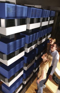
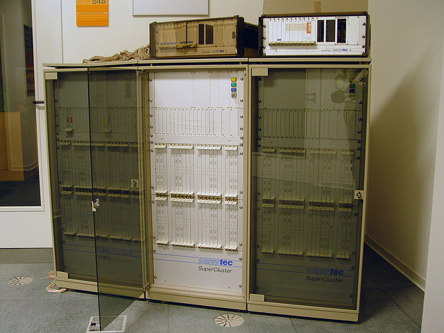
Sorry, but I have to rave a bit over its case design. I first saw it at CeBit fair 1995, when is was on display at the “IF forum design” (I explained that in the Parsytec intro already). I was literally pulled through the room and stood in front of it for minutes.
It looked like a typical FROG design work (Famous for the NeXT cube, Apple //c, some 68k Macs, SPARC Stations and much more) and I told this everybody who asked… but I just figured out I was wrong and it was actually designed by a relatively small studio called Via 4 Design.
The grey L-shaped base/back is made of sheet metal and contains the power supply in the base, a tiny bit of logic (described further down) and 2 big fans in the back.
The big blue main body is made of cast metal – no puny plastic crap. Yes, it’s heavy.
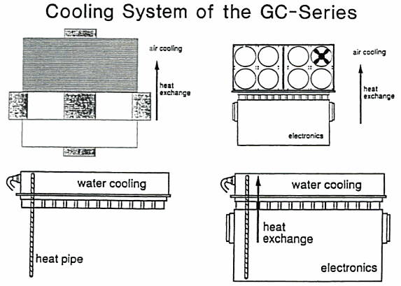
At first sight everybody thinks “hey, that’s a clever design, using the case as a heat sink!”. That’s obvious as those fingers/burlings sticking out to the left and right really do look like they are just that. And yes, as far as I was told, initially they planned to use them for cooling to circumvent noisy fans… but for some reason this didn’t work out and so they’re just a -admittedly very cool- design element.
Dissection
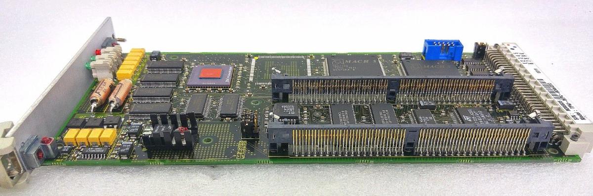
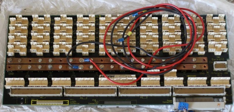
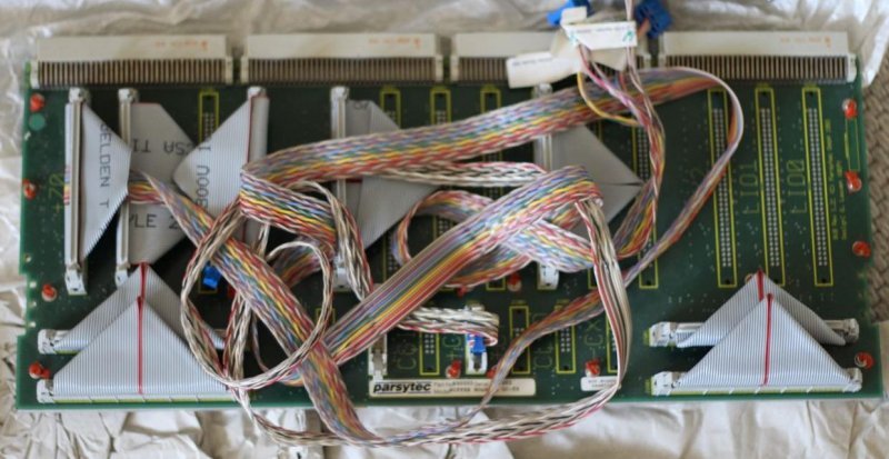
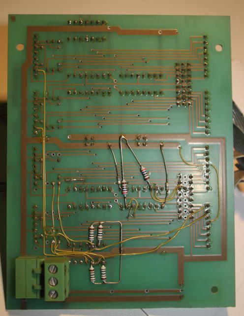
Let’s open that beauty. After loosening two screws at the back you can remove the whole back-panel holding the 2 big fans. The first you’ll see will be a rather simple, 2-layer circuit board containing the RS422 interface logic, i.e. 2 Am2631 and 2 Am2632.
This is the board removed from the case. Front:
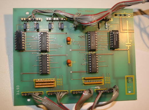
….and the back. A bit patched, some resistors added.
Those extra cables and resistors were retrofitted to allow the user to “partition” the x’plorer into either 1×16 or 2×8 Transputers. Therefore my x’plorer has a simple switch on its back to either select the full or half system. As there are 4 connectors in the back (2x TTL, 2x RS422) two users can use the system at the same time.
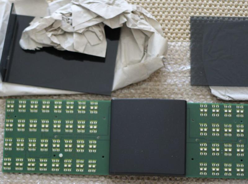
After removing the L-Shaped base from the main part, you can slide-out the blue side-panels leaving you with the dark grey frame holding the main circuit board… looking like this:
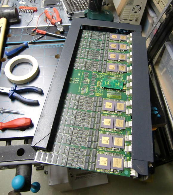
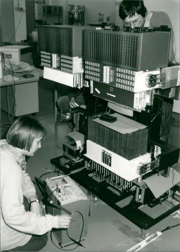
You might wonder about the ‘workshop environment’ – well, actually you need quite some tools to open the x’plorer. Like with some Italian cars ;-), you need a different screwdriver for each screw. Here’s what I remember: Allen key size 2, 2.5 and 3. Also handy are a Torx size 3 and a Phillips size 2 as well a a rubber hammer to carefully removing the dark-grey frame (consists of 3 parts).
All in all, given the wild mixture of techniques and material used, I have the strange feeling that the x’plorer was created in a somewhat shirt-sleeve approach.
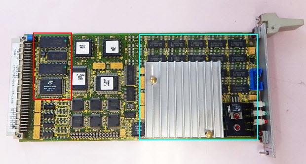
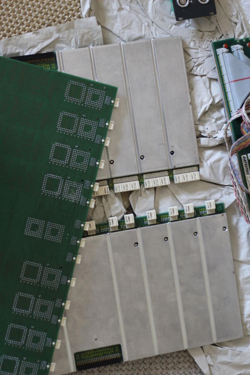
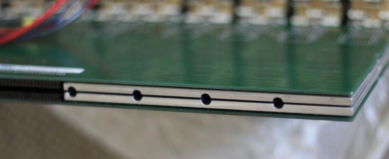
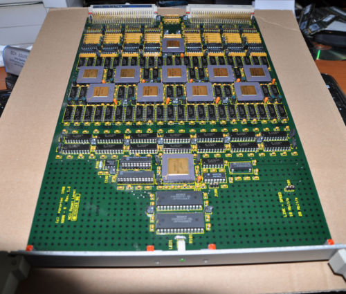
After some wiggling, careful knocking and a bit of cursing, you will have the main circuit-board laying in front of you – actually there are two boards, back-to-back, connected by a tiny backplane still hidden in the metal frame in the picture below.
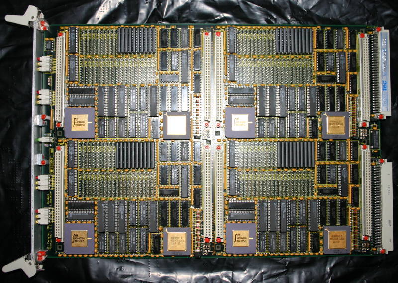
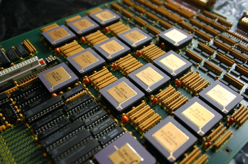
Definitely this is the high-tech part of the whole x’plorer using state-of-the-art technology of its time (1992):
A closer look
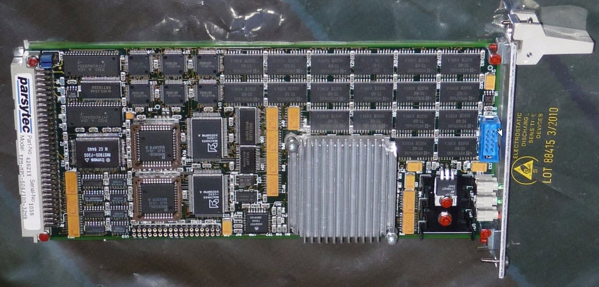
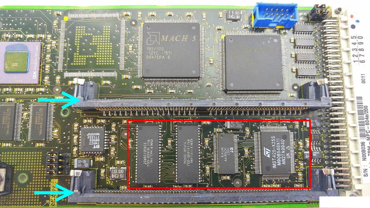
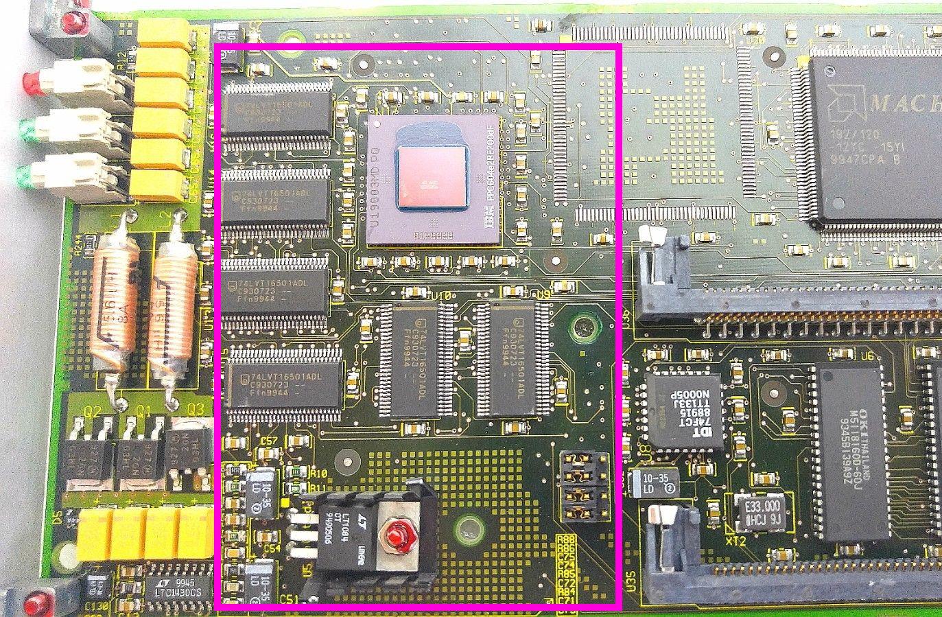
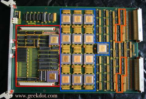
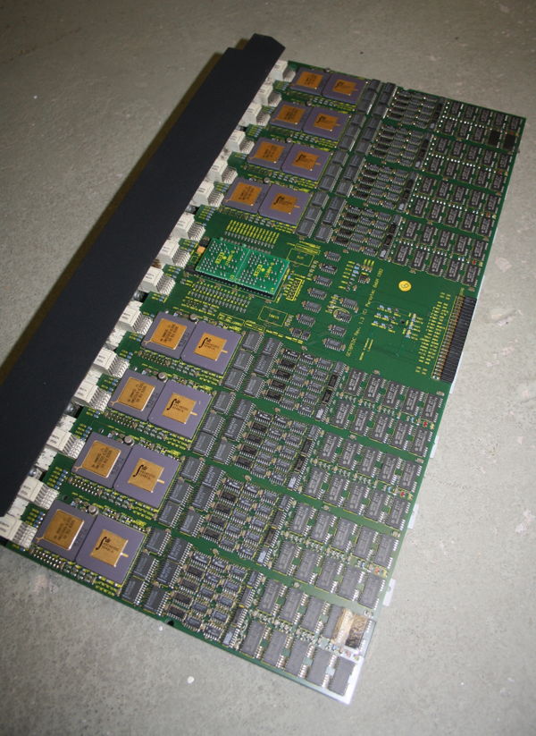
The boards layout is nice and clean. You can understand its design by simply looking at it – so let’s do so. Here’s a top-view of 3 ‘Blocks’ or ‘Columns’ as an example… all 16 look the same:
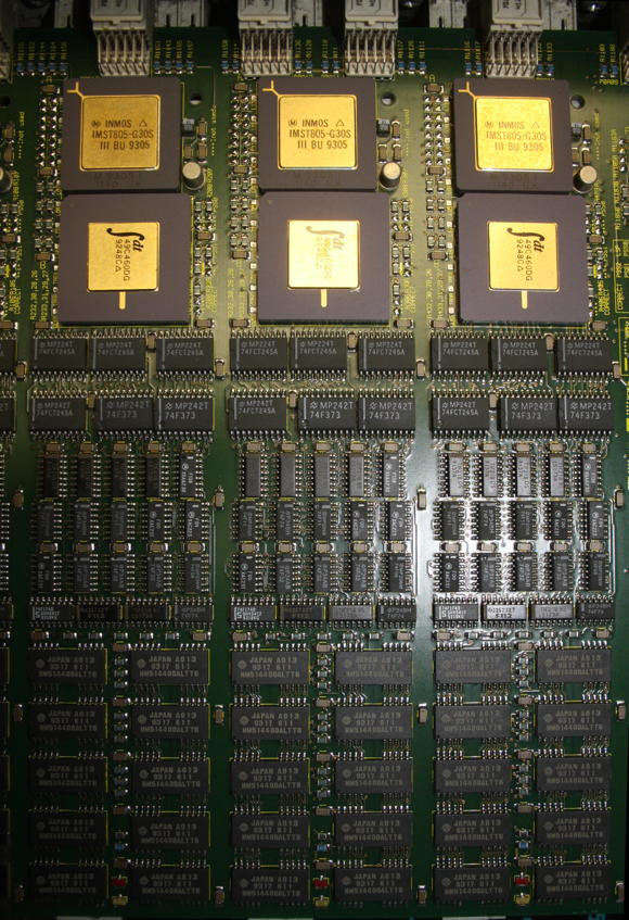
At the Top there’s the T805-30MHz Transputer. Right below is an IDT49C460 which is a 32-bit Error Detection and Correction chip which generates check bits on a 32-bit data field. Then there a lots of buffers and drivers which connect to the 4MB of RAM below them (80ns, so 4 cycle speed). Nice little feature: 2 SMD LEDs for error and running.
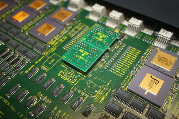
On each side, between 4 of those ‘blocks’ are two of those little circuit boards seated in 2 sockets (labelled ‘U1004’ and ‘U1005’). These are hard-wire replacements for the normally installed C004 link switches. Normally means if this cluster would have been installed in a GigaCube, there would be 4 C004s on each cluster allowing free and dynamic configuration of the Transputer network topology. So in an x’plorer you have to live with a fixed 4×4 network, which is not bad, because configuring 4 C004s can be painful 😉
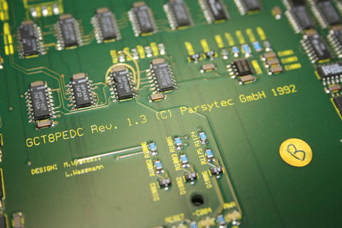
At the same spot, there’s a nice marking of the ‘fathers’ of this board, namely Mr. M.Vyskcocil and L. Wassmann.
Also, the official product name of this board is “GCT8PEDC” and it’s Revision 1.3.
The “other x’plorer”
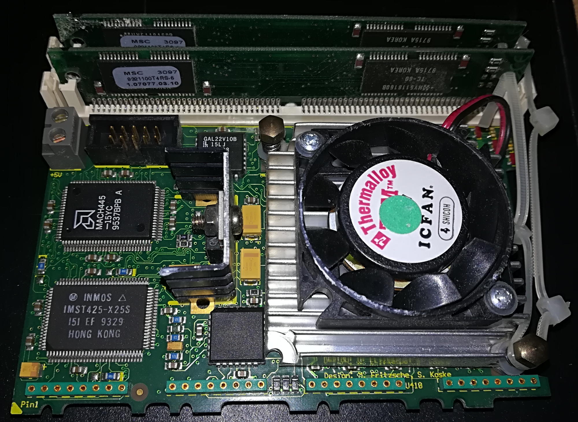
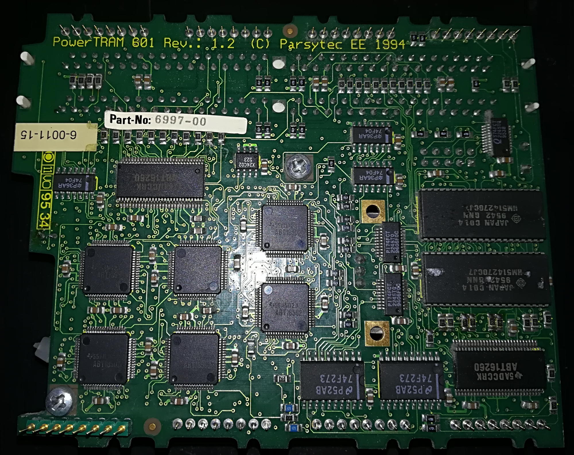
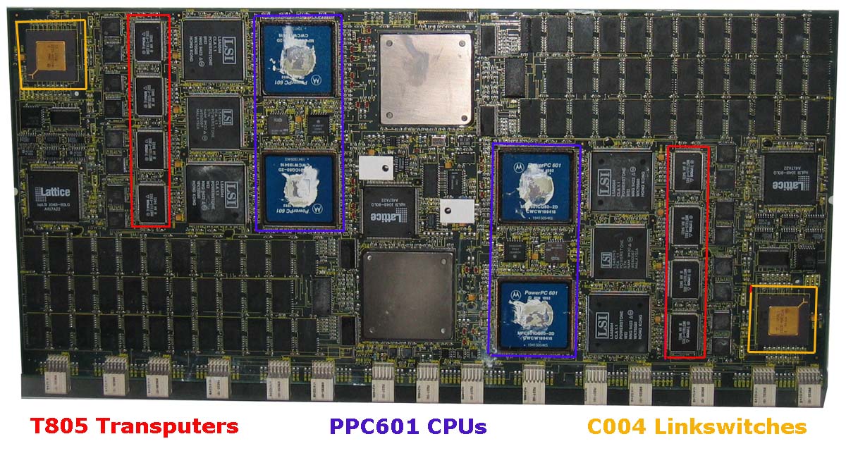
Well, yes, there was another x’plorer in existence. As with the GC-system, Parsytec later offered the “PowerXplorer”- you may guessed it already: It used the cluster from the PPC601 powered GC systems. I wrote a dedicated post over here about those hybrids, bastards, you-name-it 😉
Let’s roll
Now that we know what’s inside that beautiful case, let’s see if it’s still working. As mentioned before, Parsytec had a special way of resetting the Transputer(s). Instead of resetting all the Transputers in the network the same time (like INMOS did), Parsytec systems had been designed that each Transputer can reset its 4 direct neighbours. So you need to load a special software into a Transputer to do so.
That said, after powering-on the system, all Transputers will be reset automatically. This is the only chance to run standard Trasputer tools like ‘ispy’… once.
So I connected my trusty old Gerlach card to my selfbuilt RS422 interface and brought a cable from there into the x’plorer.
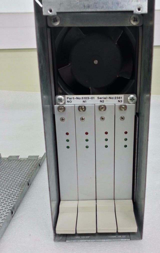
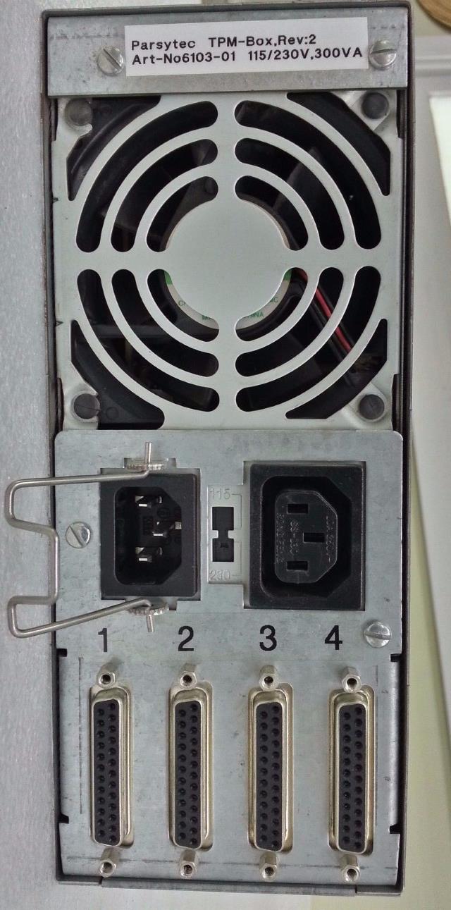
At its back, the x’plorer features four 8-pin sockets made by LEMO (Sockets are EGG.2B.308, so the plug might be FGG.2B.308 I guess) lloking like this:
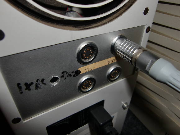
If you’re lucky enough to own one of those expensive plugs/cables, this is the wireing:
      1        1 Reset out+    2 Reset out-
   2     8     3 Link out+     4 link out-
  3       7    5 Link in-      6 Link in+
   4     6     7 Reset in-     8 Reset in+
      5
I you don’t have a LEMO plug, use the 2×5 sockets inside the x’plorer case right behind the LEMO sockets. Their pin-out should be:
10  RO+  RO-  9
 8  LO+  LO-  7
 6  NC   NC   5
 4  LI-  LI+  3
 2  RI-  RI+  1
Now let’s call ispy and see what happens…
Using 150 ispy 3.23 | mtest 3.22
# Part rate Link# [ Link0 Link1 Link2 Link3 ] RAM,cycle
0 T800d-24 265k 0 [ HOST 1:0 ... ... ] 4K,1 1024K,3;
1 T805d-30 1.3M 0 [ 0:1 2:1 3:2 4:3 ] 4K,1 4092K,4.
2 T805d-30 1.8M 1 [ 5:0 1:1 6:2 7:3 ] 4K,1 4092K,4.
3 T805d-30 1.8M 2 [ 7:0 ... 1:2 8:3 ] 4K,1 4092K,4.
4 T805d-30 1.8M 3 [ 6:0 ... ... 1:3 ] 4K,1 4092K,4.
5 T805d-30 1.8M 0 [ 2:0 9:1 10:2 11:3 ] 4K,1 4092K,4.
6 T805d-30 1.8M 2 [ 4:0 11:1 2:2 ... ] 4K,1 4092K,4.
7 T805d-30 1.8M 3 [ 3:0 10:1 12:2 2:3 ] 4K,1 4092K,4.
8 T805d-30 1.8M 3 [ ... 12:1 ... 3:3 ] 4K,1 4092K,4.
9 T805d-30 1.8M 1 [ ... 5:1 13:2 14:3 ] 4K,1 4092K,4.
10 T805d-30 1.8M 2 [ 14:0 7:1 5:2 15:3 ] 4K,1 4092K,4.
11 T805d-30 1.8M 3 [ 13:0 6:1 ... 5:3 ] 4K,1 4092K,4.
12 T805d-30 1.8M 2 [ 15:0 8:1 7:2 ... ] 4K,1 4092K,4.
13 T805d-30 1.8M 2 [ 11:0 ... 9:2 ... ] 4K,1 4092K,4.
14 T805d-30 1.8M 3 [ 10:0 ... 16:2 9:3 ] 4K,1 4092K,4.
15 T805d-30 1.8M 3 [ 12:0 16:1 ... 10:3 ] 4K,1 4092K,4.
16 T805d-30 1.8M 2 [ ... 15:1 14:2 ... ] 4K,1 4092K,4.
Tadaa! There they are: 16 30MHz Transputers running at full steam ahead! Some intense brain-boggling hours later, I was able to draw a “mesh-map”:
Host
|
4---1---3---8
| | | |
6---2---7--12
| | | |
11--5--10--15
| | | |
13--9--14--16
After this ispy run you can’t reset the network again if you don’t use proper Parsytec tools… or Helios.
So quickly running the ispy output through my little Perl script (available in the Helios chapter on this page), some small adjustments and here it is, the Helios network map:
Network /Net {
Processor 00 { ~IO, ~01, , ; system; }
Processor IO { ~00; IO; }
{
Reset { driver; ; pa_ra.d }
processor 01 { ~00, ~02, ~03, ~04; }
processor 02 { ~05, ~01, ~06, ~07; }
processor 03 { ~07, , ~01, ~08; }
processor 04 { ~06, , , ~01; }
processor 05 { ~02, ~09, ~10, ~11; }
processor 06 { ~04, ~11, ~02, ; }
processor 07 { ~03, ~10, ~12, ~02; }
processor 08 { , ~12, , ~03; }
processor 09 { , ~05, ~13, ~14; }
processor 10 { ~14, ~07, ~05, ~15; }
processor 11 { ~13, ~06, , ~05; }
processor 12 { ~15, ~08, ~07, ; }
processor 13 { ~11, , ~09, ; }
processor 14 { ~10, , ~16, ~09; }
processor 15 { ~12, ~16, , ~10; }
processor 16 { , ~15, ~14, ; }
}
}
Obviously you have to ‘compile’ a .map file out of that and adjust your initrc file – all this is described in the above mentioned Helios chapter.
When you have done everything correctly, Helios will happily boot your x’plorer and you can enjoy the mighty power of 16 (well, 17) Transputers!