[UPDATE 2025 – got a CacheDoubler! 😍 See further down for added details]
Apple Performa and PowerMac models 5400/6400 used a mainboard code-named “Alchemy“. The same board, sometimes with some changes, was used in different Mac clones like the UMAX Apus 2000 & 3000 series (SuperMac C500 & C600 in the US) and PowerComputing PowerBase.
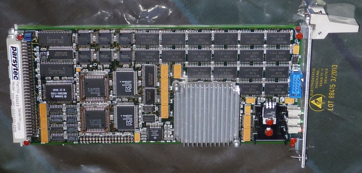
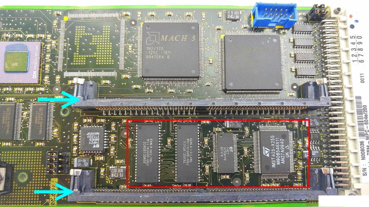
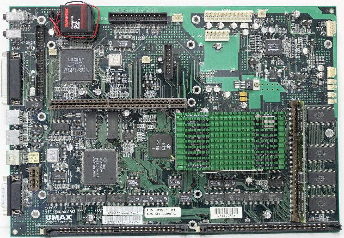
One fine day I got an UMAX Apus 2k, which uses a derivate of this board, re-cristened to “Typhoon” which you can see here in it’s full beauty:
| Processor |
|
Only Power Computing and Umax can be upgraded |
| Systembus | 40 MHz | fixed |
| L2-Cache | Slot for 256k or 512k L2-Cache | |
| RAM | 5V DIMM 168 Pin 60 ns (EDO)
|
|
To the limit!
So being the way I am… I had to optimize it. Jus can’t help it 😉
Here are the steps I’ve taken – in the order of making sense the most and being less difficult:
RAM
Simple rule: The more, the better.
This will get you the maximum performance – not in speed, but you can run memory-hungry applications without swapping (virtual memory) which is a major PITA and drags down everything.
That said, finding the correct RAM is also a pain because this board uses now very obsolete 5V buffered 168-pin DIMMs. 5 Volt is already hard to find – but the buffered version is even worse.
You can check that by looking at the coding keys (“groves”) at the DIMMs bottom:
The UMAX/SuperMac board can handle two 64MB DIMMs… if you can find & afford them.
L2 Cache
A “Level 2” cache is a must-have on all PPC machines. AFAIK UMAX/SuperMac did not sell their clones without one – Apple certainly did.
If your machine doesn’t have one, get one ASAP!
If you can get a bigger one than the one you have, do so!
- None to 256K – increases CPU performance about 30 %
The overall responsiveness is dramatically increased - 256K to 512K – adds about 20% performance.
- 512K to 1MB – need this SIMM! Mail me 😉
Umax offered an optional CacheDoubler PCB plugging between the socket and the CPU. It features an 1MB L2-Cache and upped the bus-clock to 80 MHz. AFAIK it came as standard in the UMAX C500x/C600x models.
Of course these are unicorns now and rare as chicken teeth.
NB: There are some caveats about the L2 cache discussed further down…
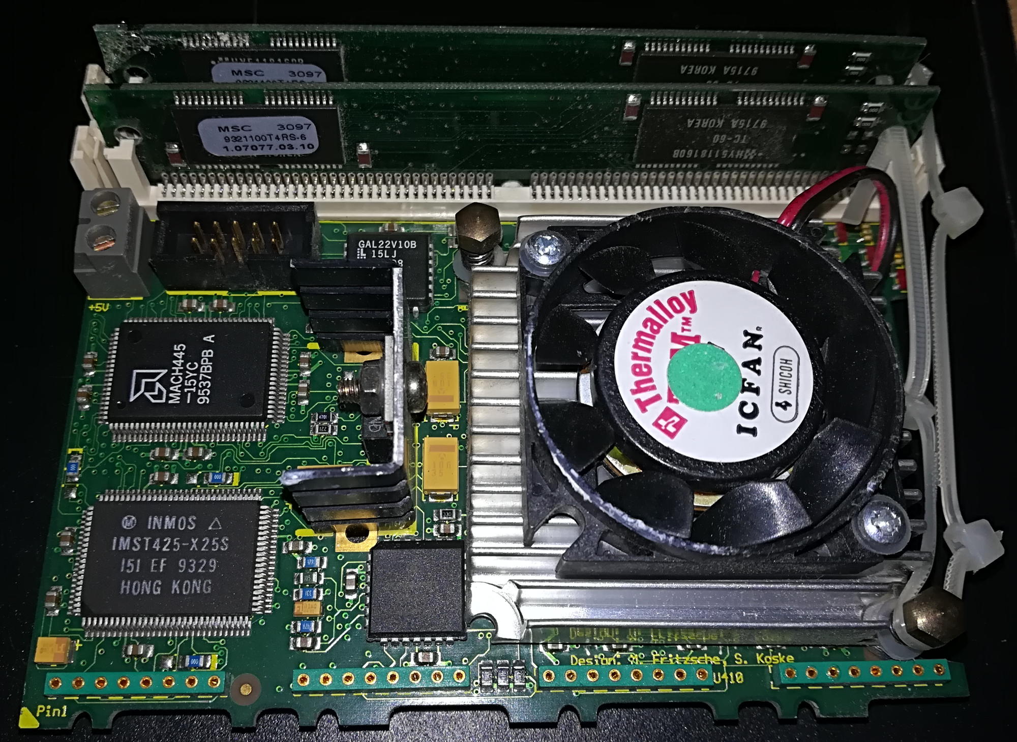
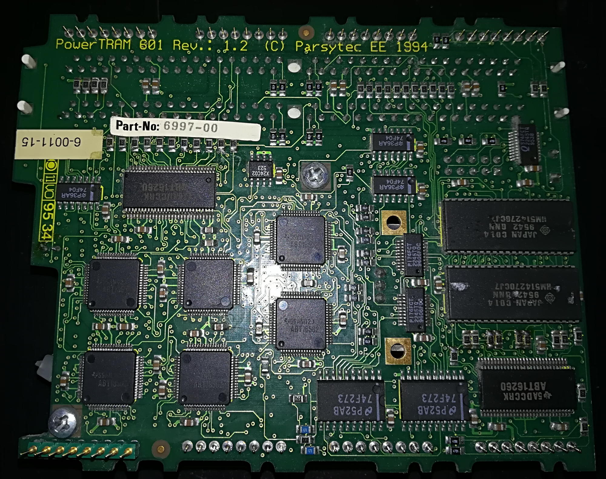
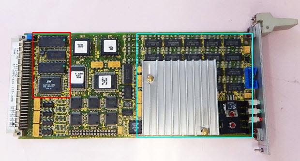
Faster CPU
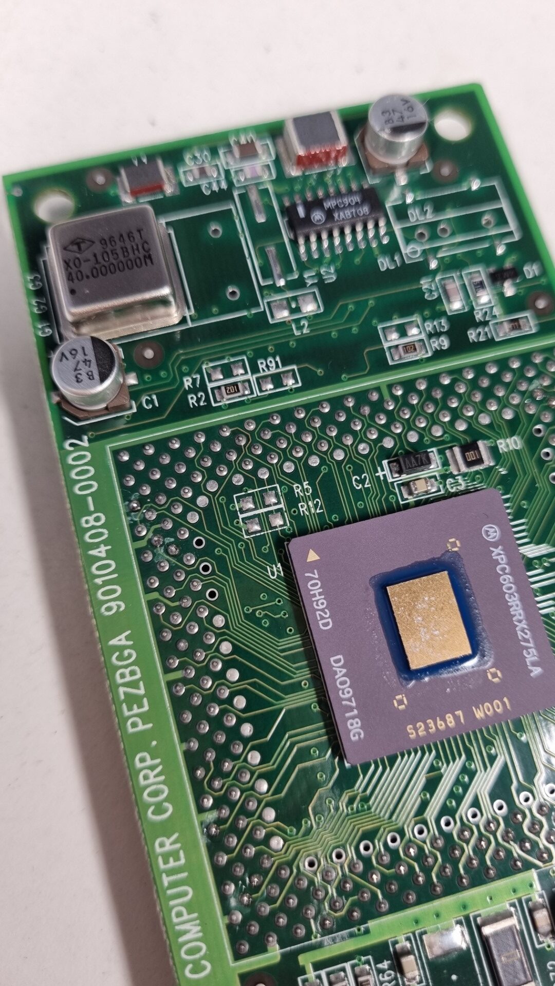
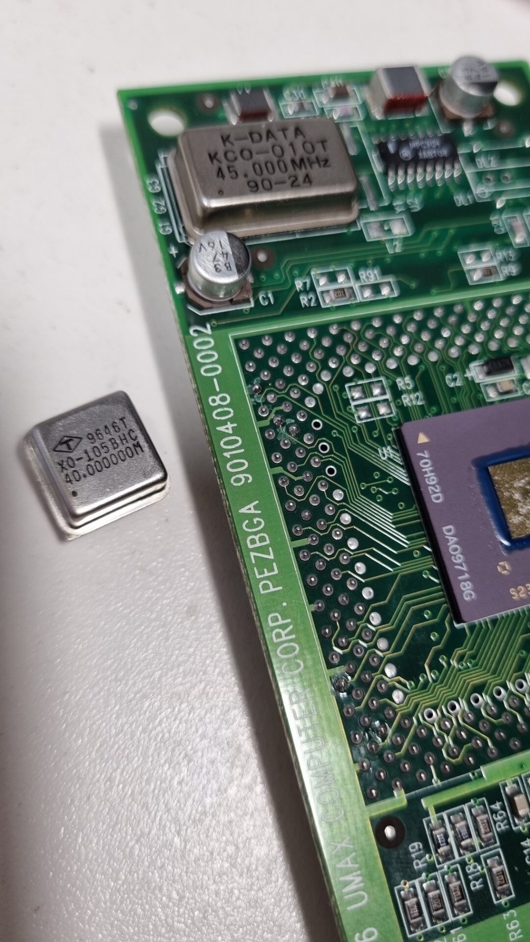
Yes, this board has a ZIF socket like the Pentiums did back then. And as such, you might be able to find a faster one. But unlike the Intel CPUs, these come on a small board covered by a big, green heat-sink.
Underneath is the CPU (in BGA package) a bit of logic, caps, lots of resistors and an oscillator.
So even if you were unable to find a faster CPU you can still ‘motivate’ yours – read: Overclocking!
As usual with overclocking, every CPU has its limits. The experiences with the 603e(v) used by UMAX are:
- 160Mhz to max. 225
- 200Mhz to max. 240
- 240Mhz to max. 270
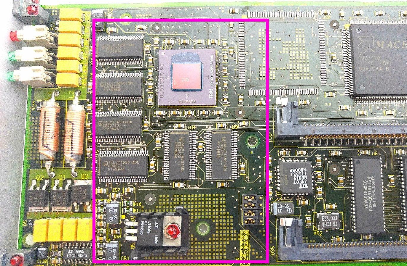
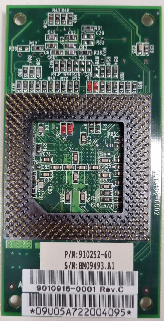
How’s that done? Quite simple (if you’re ok with soldering 0603 SMD parts) by relocating some of 8 resistors which are on the top and bottom of the CPU card… marked red on the pictures below:
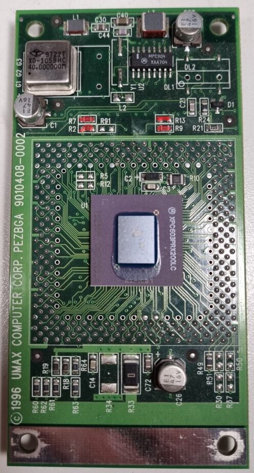
Use this table to change the CPU multiplier relative to the standard 40MHz bus-clock. There are also settings for 80-140MHz, but this is about overclocking so these make no sense whatsoever, right?
CPU Speed |
160MHz |
180MHz |
200MHz |
220MHz |
240MHz |
Busclock x
|
40 x 4 |
40 x 4.5 |
40 x 5 |
40 x 5.5 |
40 x 6 |
R1 [1.0k] |
✔ | ❌ | ✔ | ✔ | ✔ |
R2 [1.0k] |
❌ | ✔ | ❌ | ❌ | ✔ |
R3 [1.0k] |
✔ | ✔ | ✔ | ❌ | ❌ |
R9 [1.0k] |
❌ | ✔ | ✔ | ✔ | ✔ |
R6 [1.0k] |
❌ | ✔ | ❌ | ❌ | ❌ |
R7 [1.0k] |
✔ | ❌ | ✔ | ✔ | ❌ |
R8 [1.0k] |
❌ | ❌ | ❌ | ✔ | ✔ |
R13[1.0k] |
✔ | ❌ | ❌ | ❌ | ❌ |
Resistor color: Green = Bottom, Red = TOP
✔ = set, ❌ = not set
If the multiplier is not enough, you can also increase the bus-clock, too.
That way you can go up to a theoretical maximum of 300MHz 🔥
| Oszillator | 40.0MHz | 45.0MHz | 48.0MHz | 50.0MHz |
| x4.0 | 160MHz | 180MHz | 192MHz | 200MHz |
| x4.5 | 180MHz | 202.5MHz | 216MHz | 225MHz |
| x5.0 | 200MHz | 225MHz | 240MHz | 250MHz |
| x5.5 | 220MHz | 247.5MHz | 264MHz | 275MHz |
| x6.0 | 240MHz | 270MHz | 288MHz | 300MHz |
|
|
|
For maximum bus-performance don’t use odd divisors like “x4.5”
☝ If you plan to overclock your bus to 50MHz or more you have to get a faster L2 cache…
Most 256K cache SIMMs seem to have an IDT7MP6071 controller using an IDT71216 TAG-RRAM which has a match-time of 12 ns (You can derive that from the marking “S12PF”” on the chip). That`s far too slow for 50MHz bus-clock. If you would be able to change the TAG-RAM to a 8 ns Part, it would probably work.
Bigger cache SIMMs seem to feature faster TAG RAMs. Here’s a nice thread on 68kmla.org on those SIMMs.
Finally, here’s a comment from an Motorola engineer referring to the Tanzania board (but same issue) I found in a corner of the web:
“One final problem is the main memory (DRAM) timing. If the firmware still thinks the bus clock is 40 MHz (25 ns), it won’t program enough access time (measured in clocks) at 50 MHz (20 ns). There are resistors to tell the firmware what the bus speed is, so that it can program the correct number of clocks into the PSX/PSX+ to get the required 60 ns access time. For the StarMax, this means removing R29 and installing it in the R28 location for 50 MHz operation.”
I have no clue (yet) if and where those resistors are on a Typhoon board.
Update 2025
While I was asleep, my brother in arms Bolle wasn’t, so he saved the CacheDoubler which was on eBay for me! 😍
So after some days, look what the cat brought in:
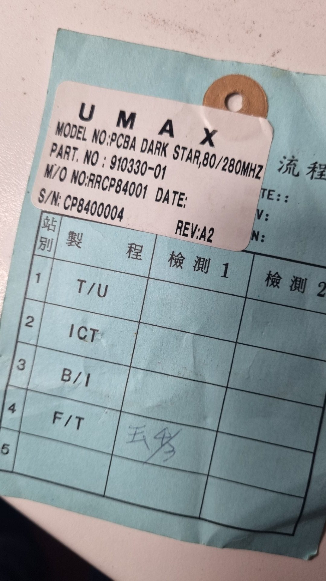
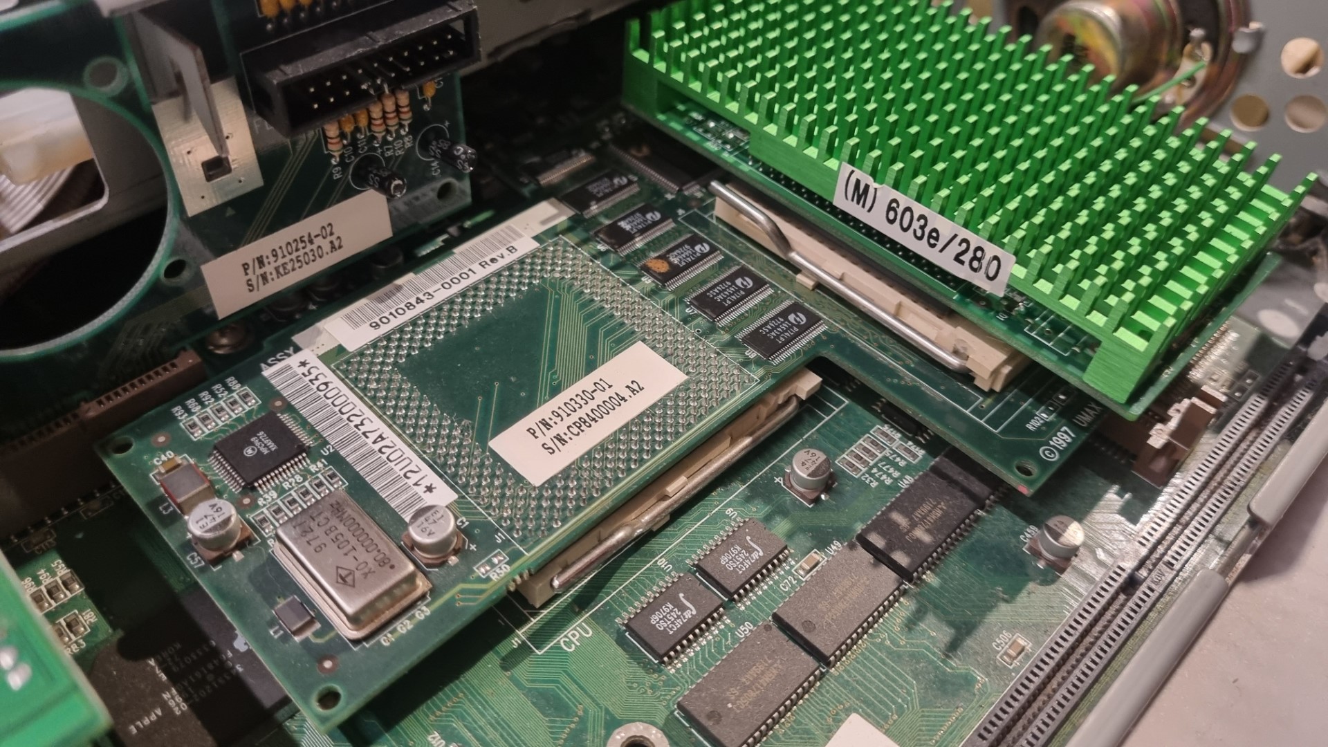
a “Dark Star” Rev A2, aka the super-rare CacheDoubler… and in it went. Ahh, what a nice view!
Crossing fingers, power on, aaaaand:
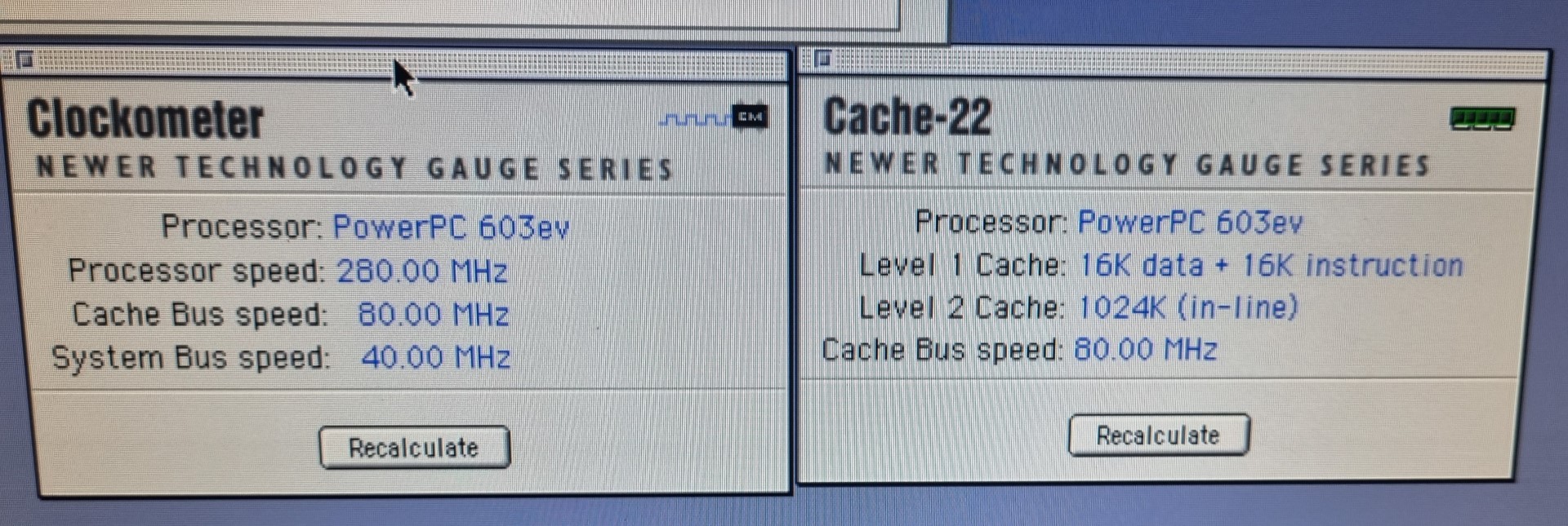
Woo-Hoo! Full steam ahead ahead🚀!
Now the CPU is clocked at 280MHz as it was meant to be… interesting enough, my bus overclocking on the CPU module is completely ignored. So it seems that the 80MHz crystal on the CacheDoubler is overruling it – multiplying it by 3.5 to get to the 280MHz CPU clock.
There would be room for experiments e.g. setting the multiplier to 4 or up the bus to 85MHz, but a can hold myself back, given the rarity of this board 😎.
And if this would be enough of luck, I found a pair of 64MB 5 Volt EDO DIMMs nearly the same day Bolles package arrived.
So this little UMAX x500 / APUS 2000 is now filled up to the brim.
Conclusion
So, what have I done in total?
I added as much RAM I was able to find (16MB on-board, one 16MB and one 32MB DIMM two 64MB DIMMs) to get a total of 64MB 144MB which is just OKish frickin’ awesome for a 603 PPC Mac
I wasn’t able to (yet) find any bigger or faster L2 cache than the 256KB I already had installed. So that one stayed as-is.
One megabyte of 80MHz inline L2 cache, baby! All my sub-G4 PowerMacs hate this litte UMAX for that 😉
I replaced my stock 200MHz 603e CPU with a module containing a 275MHz 603ev (Even the label says 280). It has its multiplier set to 6 already… so running on a 40MHz bus is runs at just 240MHz.
My wild guess is that it was meant for the CacheDoubler mentioned above and switched to a multiplier of 3.5… [you guessed right, Axel]
So I upped the bus-clock oscillator to 45MHz resulting in a 270MHz clock – 5Mhz below the CPUs spec but the bus is not stressed too much… the system runs stable and I measured a comfortable 45°C/113°F on the heat-sink.
This mod will be ignored by the CacheDoubler. So even the modded CPU module now runs at 280MHz.
Here’s a Speedometer 4.02 comparison of before and after:
This shows that every CPU benchmark ran more or less those 35% faster, which are the difference of 200 vs 270MHz – even the Disk and Grafics performance increased between 7% and 10% which is also due to the increased bus-speed.
How does that fit into a greater perspective? Let’s compare to the Macbench numbers provided by user Fizzbinn in the 68kmla forum:
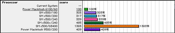
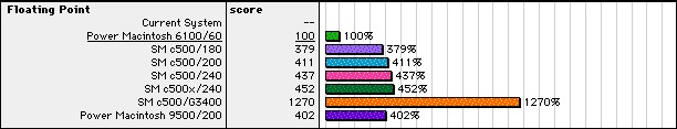
My system sorts itself 29% above the 240MHz machine concerning CPU performance… but FPU is less?!? No idea why that is.
Disk is probably a faster model than mine (WD Caviar 21600).
with CacheDoubler these numbers went up even more:

506 CPU (+37%)
474 FPU (+11%)
331 Disk (+12%)
Pretty nice for an 603e, huh? Yeah, that’s still way behind the crescendo G3/400 L2 accelerator… but therefore it’s all Supermac original 😉
What else
Well, 2 PCI slots… one for a standard 100Mbps NIC and the other one got a VillageTronic Picasso 520 which fits nicely in a System 8.5 Mac.
I tried a PCI USB card… that lead to constant boot-crashes. I should have google’d that first, else I would have known that “Although CacheDoubler does great things for performance, field reports indicate you cannot use a USB PCI card with CacheDoubler installed.” 🙄
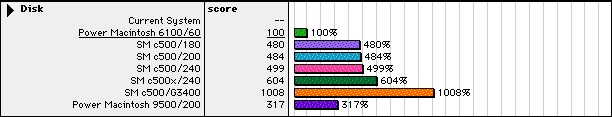
All my benchmarks were made with the original 1.6GB Western Digital IDE harddrive… which started to knock after a lot of read/write and installation experiments. So I tried other solutions:
- BlueSCSI – works fine but is quite slow (124% in MacBench 4.0)
- IBM DDRS 34560 – 4GB SCSI harddrive, pretty noisy but at least 279%… still slower than the IDE
- Found a super silent 40GB IDE drive (Maxtor “DiamondMax Plus 8”) in my “Garbage Pile” (aka basement) which was detected by Mac OS immediately. And it delivered a whopping 508% speedup against the PMac 6100 base.
So this Maxtor hard drive will be the system drive. HFS+ 40 Gig should be enough for experimenting.