Intro
Transputers were created to control everything. They were not just CPUs… they could do the video output, control interfaces or even storage devices. So no wonder there were ISDN and SCSI controllers available using transputers.
One of those transputer-sporting controllers was the AVM B1 active ISDN card. Back in the PC-AT days, handling the ISDN protocol and traffic could easily bring down your super-cool 80386/25 without a problem, especially if this machine should also fulfill server tasks.
So active (vs. passive) ISDN cards were the cure to that issue. They featured a CPU of their own with some RAM to buffer the data coming in at the maximum ultra-fast rate of 128kbps 😉
In case of the the AVM B1 the CPU was a transputer (T400) and that had reign over a whopping 1MB of RAM! When the card was installed and the DOS driver booted, it actually loaded the transputer code onto the card like any normal transputer card would be fed with code – behaving like an Inmos B004 card and even using the same port addresses.
So in fact, the AVM B1 is a transputer card featuring an ISDN-part connected to one of the transputers links.
Using the usual tools for finding and checking a B004 compatible card shows this
> ispy | mtest Using 150 ispy 3.21 | mtest 3.21
# Part rate Link# [ Link0 Link1 Link2 Link3 ] RAM,cycle
0 T400b-20 43k 0 [ HOST ... ... ... ] 2K,1 1022K,6.
Weapon of choice
Ok, cool – so where do I get this card?
Well, AVM is still very alive-and-kicking but they’re not building these cards (using transputers) anymore… even if they wanted to, Inmos/SGS killed the transputer back in 1993. So eBay is your friend.
Anything to watch out for?
Yes! AVM build(s) 4 major versions of the B1: V1 to V4.
V1.x – Available as ISA and MCA version. The perfect choice! Everything important is socketed, no SMD parts.
V2.x – ISA version only. CPU & RAM is SMD. Ready to play with but not much to mod.
V3.x – ISA & PCI version. Updated version, same features like V2.x
V4.x – PCI version only. No transputer anymore. “StrongT” Controller… might hint towards a StrongARM based thingy.
Again: If you want to do all the hacks described here you have to get a Version 1.x card!
Enhance it! This is the easy part…
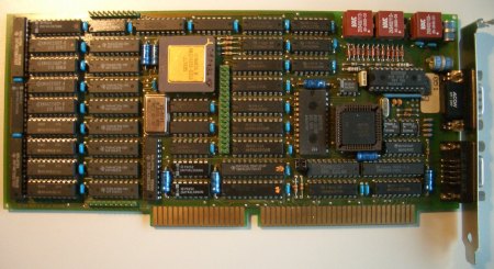
Ok, so I assume you fought hard to get a V1.x B1… it should look like this:
(If you acquired an V2.0 card which is smaller and has lots of SMD parts on it, check out Jonathan Schillings page (German), who did all the mods described here with a V2.0 card)
If you have your card in front of you, you might spot some differences. These are the first two and most obvious “mods”:
- Change the T400 CPU (e.g. to a T425 or even T800)
- Add more RAM
The T400 is OK to begin playing with this card, but it only offers 2K internal RAM (vs. 4k in the T425/800) as well as it has only 2 links: One connected to the C012 (and this going to the ISA interface) and one is available. I was under the impression, that AVM might use the other link to interface to the ISDN part, but that seems to be memory-mapped.
Changing to a T425 gives you more internal RAM (=speed) and the possibility to use 3 external links to talk to more connected transputers.
A T800 would be the top-of-the-hill, featuring an FPU which will speed up your Mandelbrot tremendously.
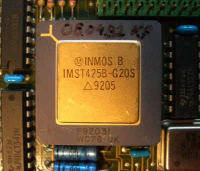
So here’s my T425 which replaced the stock T400. At about 8-10 Euros you should be able to get one at ePay…
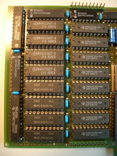
Next up, the RAM. Albeit the standard 1MB are plenty enough for nearly all fooling-around you might plan, there’s another Axel-Law to be followed: “If there’s an empty socket, fill it!”.
Also if you’re going serious and think about running the Helios OS on this card, you’ll better have 2MB!
You need to get eight 256Kx4 chips – they’re pretty common. They should be faster than 100ns… you’ll read later why.
The eagle-eyed reader might spot the different makers of the RAM chips. That’s because I’ve salvaged 2 old ISA-VGA cards (each 512k) for the chips. All are spec’ed at 80ns.
Another run of the transputer find/check-tools now shows this
> ispy | mtest
 Using 150 ispy 3.21 | mtest 3.21

# Part rate Link# [ Link0 Link1 Link2 Link3 ] RAM,cycle

0 T425b-20 43k 0 [ HOST ... ... ... ] 4K,1 2044K,6.
Not bad, huh? But there’s room for improvement… the RAM is accessed extremely slow, set to 6 clock cycles which is very conservative, even for 100ns RAM parts.
Faster RAM – The not-so-easy part…
Ok, up to here it was a piece of cake, wasn’t it? Now we’re switching to hard-core mode 😉
RAM-Access speed-up
For this you’ll need
- Some soldering know-how – and a solder-iron of course
- A calm hand
- A continuity-tester or multimeter
- A thin cutter
- the pinout of a transputer (available in the data sheet (PDF))
As said before, the RAM access is very slow. It’s set to 6 clock cycles which is recommended for 150ns parts even at 20MHz. So for a start we should be safe going down to 5 cycles even with the standard 100ns RAM chips…
The RAM is controlled by the transputer itself – something the Intel-World introduced with the AMD Opteron years later!
When booting, the transputer checks how his “MemConfig” pin (position C8) is connected to the MemAD[3-7] pins to determine the RAM speed. The AVM B1 has its “MemConfig” connected to MemAD7 (position K10) which we want to change to MemAD6 (J8) in the first step.
The AVM B1 is a 4-Layer card and unfortunately the wire connecting those two pins is running in the 2nd layer from the back.
To find the trace we have to cut, hold the card in front of you looking at the component-side – like the first picture on this page. Now flip it vertically. You’re looking at the solder-side, the external connectors pointing to the left.
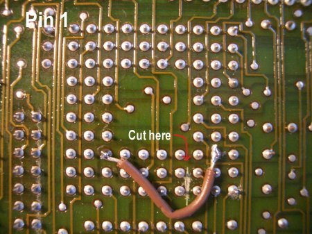
A closer look at the transputer pins shows you where to cut and the wire connecting “MemConfig” with “MemAD6” – Pin A1 is in the upper left corner, counting down[123456789,10], letters right [ABCDEFGHJK]!
The cutting is a delicate thing to do. So be very careful not to cut too deep. I did it by cutting carefully once or twice and then checking with a continuity-tester if MemConfig and MemAD7 are still connected. Repeat until the connection is broken.
If everything went fine solder a wire between the two pins. Don’t make the wire too short, so we can change/move it anytime later. Another test shows this now:
Using 150 ispy 3.23 | mtest 3.22

# Part rate Link# [ Link0 Link1 Link2 Link3 ] RAM,cycle

0 T425b-20 43k 0 [ HOST ... ... ... ] 4K,1 2044K,5.
Yay! RAM’s accessed a bit faster now.
If that works and you’re like me (squeezing out the last drip of everything) you can try connecting to MemAD5 (J9). It worked for me.
Faster Link Speed – Not for the fearsome!
The next thing being rather sub-optimal is the link-speed… 43k/s is dran slow.
Using 150 ispy 3.23 | mtest 3.22

# Part rate Link# [ Link0 Link1 Link2 Link3 ] RAM,cycle

0 T425b-20 43k 0 [ HOST ... ... ... ] 4K,1 2044K,5.
That’s because it’s locked to 10Mbit/s by AVMs design even 20Mbit/s would be possible. Again, the transputer gets its configuration during boot-time via special pins. In this case LinkSpecial(A2), Link0Special(B4) and Link123Special(A4).
Not a big deal, but in case of the AVM B1 it’s not solvable by simply putting those pins high or low. That damn card is -again- a multilayer card and one of those layers is a ground-layer. No way in cutting a trace here.
The only solution is an in-between socket… a calm hand and pincers >:-)
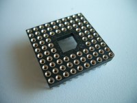 Ok, first you have to get another 84-pin socket. It’s not so easy anymore to find those… luckly, I had one spare collecting dust.
You might find an alternative socket meant for a Motorola 68881/2 FPU – but make sure it also has the inner pin-rows connected. Normally the 68881/2 has 8 pins less!
Another possibillity would be making a socket by glueing 10×1 pin-rows together. Not pretty but should do the job.
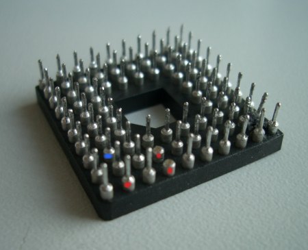
For the second step, you’ll need a caliper and (again) the transputer pinout. Orientate the socket so that pin-1 is in the upper left corner (the picture above shows this by the angled-corner in the center of the socket).
Now identify the pins LinkSpecial(A2), Link123Special(A4) and Link0Special(B4) as well as one VCC-Pin of your choice (I went for C2). We need to connect those 4 pins, pulling all Link[n]Specials high… which gives us 20Mbit/s link speed!
Note: If you plan to use the B1’s external links, you might consider not to change the external link-speed – read more about this in the next chapter.
In this case do not change Link123Special(A4).
So carefully cut the thin part of the pins A2, A4 (see note above!) and B4. Use a rasp/file to shorten the pin down to the thicker base (so the remaining part can’t connect to the original socket).
This is how it looks already having A4 & B4 cut off, A2’s still due (all marked red) – Do not cut the VCC-pin (C2, marked blue)! :
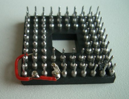
When everything’s nicely cut, use a wire to connect them together – it’s a bit tricky to solder between the pins, so use a fine tip.
When you’re done, the socket should look like this:
Now double check the modded pins for shorts to their neighbours!! Not doing so might kill your transputer/card!!
Cool! Were half done. For the third step we need to adjust the other side of the link accordingly. “The other side” is the Inmos C012 link-adaptor sitting in the lower right corner of the card -close to the ISA connector- labeled “IMSC012-P20S”.
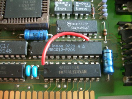
Identify pin-15 and use a thin caliper to cut its leg as close to the board as space allows it. Bend the remaining leg up and check that there’s no connection to the card anymore.
Now solder a wire going from pin-15 to some VCC source. I’ve chosen Pin-20 of the 74ALS245 next to the C012. This is how it looks on my card:
[Note: Make your wire long enough so you can reach some GND pin with it. So you can reverse the mod easily.]
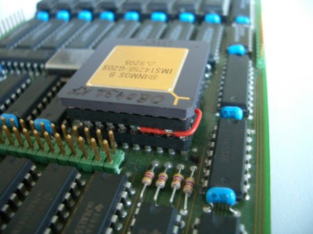
We’re nearly there! For the forth and last step, plug your transputer into your in-between socket and the whole thing into the original socket on the card like this:
Done! If everything was done right the usual tools should give you some serious number (well, it’s still far away from the theoretical 1.7Mbit/s, but at least 8.8 times faster than before):
Using 150 ispy 3.23 | mtest 3.22

# Part rate Link# [ Link0 Link1 Link2 Link3 ] RAM,cycle

0 T425b-20 378k 0 [ HOST ... ... ... ] 4K,1 2044K,5.
378k/s is faster than my crappy Gerlach-card (@239k), even the AVM is also just using 8 data-lines of the ISA bus (being a 16-bit card it only uses 4 lines from the AT bus… for IRQs 10-13).
So… what else can be done?
The external Connector
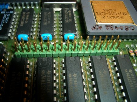
The AVM B1 v1.x cards feature a mysterious (green) connector:
It’s undocumented… up to now 😉 I just started tracing all the connections, but I’m happy to say that even AVM did everything possible to cripple the B1 card, they did not dumb it down completely:
Link[123] & Reset (not inverted!) are brought to the outside!! Error and Analyse are hold to GND, though.
Note: That said, AVM wouldn’t been AVM if they didn’t save a dime… the external links are buffered (at least) by a comparably slow 74BCT541 octal buffer.
This offers a signal propagation delay of ~9ns while INMOS recommended to use “F” type buffers, which offer a speed of about 3-4ns. So 20mbps are too fast for this chip. 10mbps should work though.
Here are my findings so far: [work in progress]
I started counting pins from the transputer, zig-zag, downwards. Interesting things coloured green.
 1 2

o o

reset o o

o o

o o

o o

o o

PEB2070
o o (to its pin 10)
Link3Out o o
Link2Out o o
Link1Out o o
Link3In o o
Link2In o o
Link1In o o
GND o o
o o
GND o o
o o
33 34

