Category Archives: DIY Projects

DIY Projekts Hardware

DesperRAM

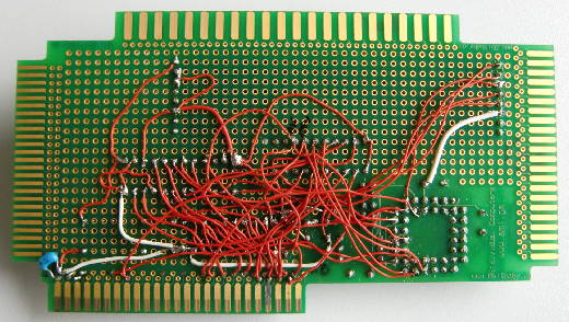
You might have been in the same situation: Some piece of old hardware could be upgraded (aka pimped) with more RAM, but there’s no place in the world to get that type of RAM needed.

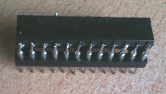
In my case it was 1Mx4 DRAM in a DIL packaging. It’s hard to come by those in a ZIP packaging – sometimes used on AMIGA RAM cards – but DIL is next to impossible.

Well, when 1Mbit RAM chips were introduced, the industry switched to SIMMs anyway… and that’s where you find those. For the DespeRAM, SOJ packaging is what you want. SOJ (sometimes also called J-Lead) means there are short pins on the IC but they’re bend inwards under the chip… pretty much like PLCC pins.

What you need for this stunt:

  • Desperation. Lots of it.
  • A hot-gun (for getting the SOJ chips off the SIMM module)
  • A fine tip on your solder-iron. Very thin solder led (e.g. 0.5mm)
  • DIL sockets for your desired piece of crap^h^h^h^h vintage hardware
  • Wire, also thin (I used 0.6mm)

Preparation:

Clean desk. Good lighting. A steady hand (no coffee or drugs – I assure you, it won’t work. I tried it ;))

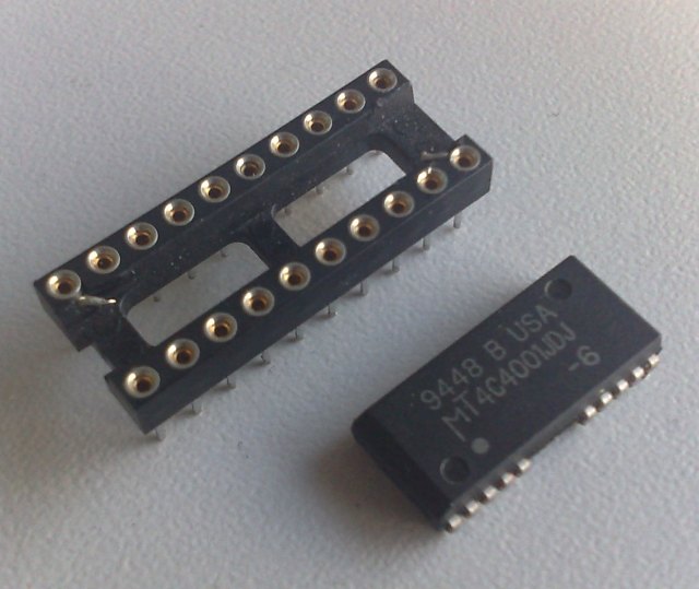
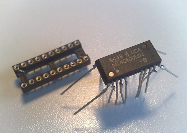
Ok, so first of all get out the hot-gun and carefully get the ICs off the module. Here’s a single chip and the socket it should be mated to

desperRAM1

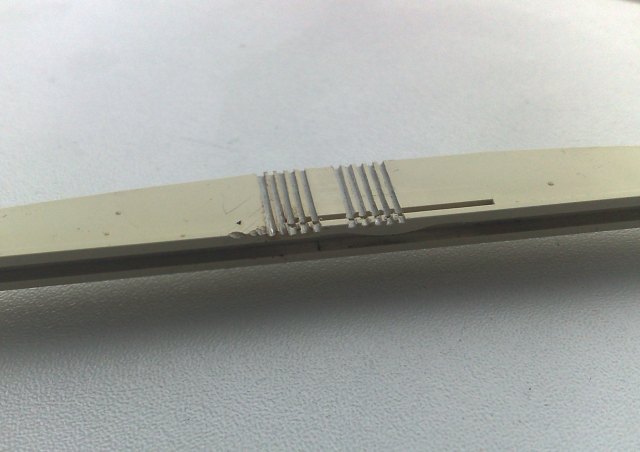
Bend the pins and straighten them. I used a needle to pry the pins upwards a bit and did the rest with tweezers. Now you have the exact spacing of the pins on your chip. Use that for building a “pin aligning tool”. I’ve used a piece of plastic and a fine saw to cut 10 grooves into it. When done, it looked like this:

desperRAMtool

Now find something on which you can fixate the chip to (still being movable). I used a block of wood and a rubber band. This worked quite well. This way, you can always adjust the position of the chip when needed.
It’s time to cut some pins. For the start I went for about an inch long – place them into your self-made tool and fix them with a piece of self-adhesive tape (Scotch in USA, Tesa over here ;)).
Now put some solder on the chip’s pins as well as on the freshly cut DIY-pins.
Carefully position your tool so that the pins do have good contact.

If you did everything right, a short contact with the solder iron tip should be enough to solder the new long pin to the original one. When you’re done with all pins it should look like this

desperRAM2

As you can see, I did already start to bend the new pins to fit into the socket. It’s a bit try-and-error to get the right angle. Be careful to avoid the pins touching each other or even break when being bent. Re-fitting a single pin can be a major pain in the a**!
Now you need to cut the pins into a reasonable length. First bend them into position – constantly checking against the socket. When all pins are ok – start cutting from one side to the other, bit for bit until you got the perfect length (Use the first chip as a model for others which might follow).

The seating is a bit difficult as you can’t use maximum force to push them into the socket. I used a fine caliper to actually pull the chip into the socket.

Due to the angle needed, the chip will hover quite a bit above the socket. I guess you can go lower if you go for a 90° bending – I didn’t have the patience.
Double check all connections from the original pin to the one on the socket. Also check for shorts!

desperRAM3

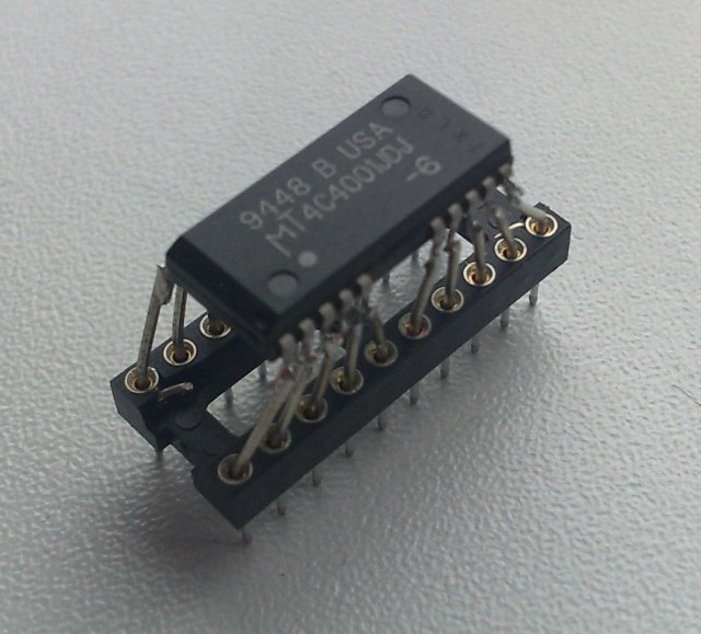
Here you have it, the ugly Franken-Chip. But hey, it didn’t cost me a dime!
That said, after soldering 160 pins, bending them and carefully pulling them into their sockets… I guess I won’t do it again 😉

Fixing scratched traces

This is the price you have to pay if you’re into real men’s hardware:

Being (falsely) identified as “old crap”, some cool things end up in the dumpsters… or worse. Being tossed around in some storage for years, probably stacked with other cards and boards, it might happen that some traces on the outer layers got badly scratched, thus making the board/card non-working. Here’s how I try to fix scartched traces… and most of the times it works:

First make sure that the circuit path (trace) is really broken – I just may look like, but isn’t.
To do this you need a volt-meter. Follow the suspected trace in both directions until you find a pin or through-hole it is connected to. Use these two points to test if the trace is still connected.

Ok, damn, it’s broken 🙁 You need three things:

  1. A sharp knife or scalpel
  2. Adhesive tape (Scotch, Tesa or whatever it’s called in your corner of the world)
  3. Conductive (silver) lacquer

Conductive-what? Conductive lacquer is actually a cool thing to play with… but be prepared: It’s not cheap (about 9-10 Euros). It comes in tiny bottles or as a pen, which is even more expensive (20+ Euros). The bottles look like this (lacquer and diluter):

ConductiveLacquer

Ok, the process is quite simple:

  1. Use the knife to scratch-off some of the coating lacquer on both ends where the trace was “cut” until you see some copper shining through.
  2. Check with your volt-meter that you actually have contact with one end and e.g. a pin on the other end of the trace. Do this for both “halves” of the cut trace.
  3. Mask the place you’re going to ‘heal’ with your adhesive tape – this prevents the conductive lacquer to run all over your board.
  4. Apply the conductive silver lacquer onto the spot you’ve just masked and let it dry (read the manual that came with the lacquer – yeah it’s unmanly but nobody will see you ;-))
  5. Using your volt-meter, check again. This time from both ends of the complete trace.

If you’ve done everything right, the  trace should work again – and so does your card/board! Yay!

Here’s how my badly scatched MiroHIGHRISC looks like in certain places – can you spot the little silver dot?

FixedPath

Final hit: Some lacquers are quite thin on silver (blame the manufacturer) so after some days the spot you just fixed might become unreliable. In this case you might repeat the procedure to get more silver to that spot.

T2C64

So here we go, C64 first. Some moons ago I was at least midwife if not the mother of the 8BitBaby manufactured by the fairies and elves over at individual computers.

This little card features 4 slot-connectors to the most used home-computer systems as well as a CPLD… and makes a perfect basis for my first C64 “cartridge” ever 😉

The schematic was taken from “Das Transputerbuch” by U. Gerlach and being put into the CPLD saving lots of TTL chips. Actually all you need then is an Inmos C012 or C011 link-interface chip, a 5MHz oscillator and some resistors and caps.
I refrained from designing a complete Transputer system but went the easy route by interfacing to a TRAM. A TRAM is a complete “Transputer system on-a-stick”, like those used in my Tower of Power. All you need for a TRAM is an interface to your system. For the C64 you would need the thing I’ve called T2C64 (aka “Transputer to C64”)

The T2C64 prototype in its full glory:

T2c64

A short overview what’s on the card:

  • The left edge is the connector to the C64s expansion slot (ignore the other edges).
  • The square black chip is the Altera CPLD mainly containing the bus-interface and the Transputer Analyze/Reset/Error signal handling. Ah, and it controls the 2 LEDs.
  • The long black chip above the CPLD is an Inmos C012. This guy interfaces an 8bit parallel bus to the serial Inmos link ‘bus’.
  • The silver thing is a 5MHz oscillator to clock the C012.
  • And finally the longish module at the top edge is a TRAM with 128KB RAM and a mucho-macho T800 Transputer.

The CPLD maps the C012 register into the memory area of 0xde00, using just 6 addresses:

  • Data in       0xde00 (56832)
  • Data out     0xde01 (56833)
  • in-status     0xde02 (56834)
  • out-status   0xde03 (56835)
  • reset/error  0xde08  (56840)
  • analyse      0xde0c  (56844)

So programming it pretty easy, still, you have to read some Inmos manuals about the protocol etc… that said the next chapters will show you some code examples I’ve slapped together just to test the hardware. All sources and binaries (.D64 image) are available in a zip file over here, obviously most of that does not make sense without having a T2C64…

Read on in the next posts for demo-code and even a video. “uuh, videos!”

1st code example

For the fun of it, here’s my first Commodore BASIC v2 program which does 3 things.

  1. Line 1-50: Initialize the Transputer and set/get its status.
  2. Line 69-110: Write (poke) some data into T’s memory and read (peek) it back.
  3. Line 128-240: Send a little program to the T and read its result.

10 PRINT"INIT TRANSPUTER"
11 POKE 56840,1:POKE 56844,0:POKE 56840,0
20 REM CLEAR I/O ENABLE
21 POKE 56834,0: POKE 56835,0
30 REM READ STATI
31 PRINT "I STATUS: ";(PEEK(56834)AND1)
35 PRINT"O STATUS: ";(PEEK(56835)AND1)
40 PRINT"ERROR: ";(PEEK(56840)AND1)

This is the Transputer POKE command (0) which tells the T that the next 4 bytes are an address followed by 4 bytes of data:

45 PRINT"SENDING POKE COMMAND"
46 POKE 56833,0
50 PRINT"O STATUS: ";(PEEK(56835)AND1)
58 :

Mind that were little endian and BASIC is using decimal numbers. So we’re POKEing 0,0,0,128 which is 0x00, 0x00, 0x00, 0x80 in hex which again is the 32bit address of 0x80000000.

59 PRINT"SENDING DATA TO T."
60 POKE56833,0:POKE56833,0:POKE56833,0:POKE56833,128
61 POKE56833,12:POKE56833,34:POKE56833,56:POKE56833,78
70 PRINT"I STATUS: ";(PEEK(56834)AND1)
79 :

Now reading back (PEEK) from 0x80000000 what we just wrote:

80 PRINT"READING FROM T."
90 POKE56833,1:REM PEEKING
100 POKE56833,0:POKE56833,0:POKE56833,0:POKE56833,128
110 PRINTPEEK(56832);PEEK(56832);PEEK(56832);PEEK(56832)

These 4 sequential PEEKs print 12 34 56 78. Yay! A very simple Ram-disk if you want.

Now something more serious. A very small programm is sent to the T and executed. Instead of peek and poke (1/0) the initial ‘command’ is the length of the program (23 in this case), so the T starts executing after he received the 23rd byte.
The program itself is trivial, after some initialisation it writes 0xAAAA0000 to link0out. The use of it is very simple. If the Transputer is working correctly the first 2 bytes will allways be “0xAA”, if it is just a 16bit Transputer (T2xx) there won’t be more than 0xAAAA. A 32bit Transputer returns the full 0xAAAA0000. Voilá, that’s a simple T-detection.
To handle timeouts end error conditions I had to do some ugly things in BASIC. Sorry, don’t blame me, BASIC v2 is just… very basic.

120:
128 DIM R(4)
129 PRINT"SENDING PROGRAM TO TRANSPUTER..."
130 FOR X=1 TO 24
140 READ T:POKE56833,T
150 WAIT 56835,1
160 NEXT X
170 PRINT:PRINT"READING RESULT:"
175 C=0
180 N=TI+50
181 IF C=10GOTO 220
189 IF TI>N THEN ER=ER+1:IF ER=10 GOTO 220
190 IF (PEEK(56834)AND1)=0 GOTO 189
195 R(C)=PEEK(56832)
200 C=C+1
210 GOTO 180
211 REM ------------------------
220 IF C=1 THEN PRINT"C004 FOUND"
230 IF C=2 THEN PRINT"16 BIT TRANSPUTER FOUND"
240 IF C=4 THEN PRINT"32 BIT TRANSPUTER FOUND"
1000 DATA 23,177,209,36,242,33,252,36,242,33,248
1001 DATA 240,96,92,42,42,42,74,255,33,47,255,2,0

Next up a bit more useful example, reading the Transputer executable directly from a binary file instead of having it in-line.

2nd code example

This example actually puts the Transputer to some sort of use… well, it’s still way beneath him but it does its job as an example.
Two tasks: a) Read the Transputer executable from disk and b) exchange data with the Transputer.

Here we go:

10 PRINT"INIT TRANSPUTER"
20 POKE 56840,0
30 POKE 56844,0
40 POKE 56840,1:POKE 56840,0
50 FOR W=0 TO 1000:NEXT W
60 POKE 56834,0
70 POKE 56835,0
80 REM READ STATI
90 PRINT "I STATUS: ";(PEEK(56834)AND1)
100 PRINT"O STATUS: ";(PEEK(56835)AND1)
110 PRINT"ERROR: ";(PEEK(56840)AND1)
140 PRINT"O STATUS: ";(PEEK(56835)AND1)

Up to here everything should be clear. Init Transputer, read stati -just to be sure.
Now we’re reading the executable (“GRAB”) from floppy and poke the bytes to the Transputer as they come flying crawling in:

150 DIM R(4)
160 PRINT"SENDING PROGRAM TO TRANSPUTER..."
170 REM READ TRANSPUTER BIN FILE
180 OPEN 1,8,2,"0:GRAB,S,R"
190 FOR I=0 TO 1 STEP 0
200 IF ST=64 GOTO 240
210 GET#1,A$:A=ASC(A$+CHR$(0))
220 POKE 56833,A
230 NEXT I
240 CLOSE 1

Ok, the Transputer binary expects us to tell it the number of integers we’re about to send to it (AN), the we send these (X) and finally re-read the results… which should all be X+7.

250 INPUT"COUNT:";AN
255 POKE 56833,AN
260 FOR AA=1 TO AN
270 PRINT"ENTER ";AA:INPUT X
280 POKE56833,X
290 NEXT AA
295 PRINT"GETTING";PEEK(56832);" RESULTS"
300 FOR BB=1 TO AN
310 PRINTPEEK(56832);
320 NEXT BB

Some final words about Transputer executables. There are many kinds depending which development system was used. Some need special loaders or bootfiles before the actual binary will be send to the Transputer. A ‘raw’ upload is only possible with binaries mostly having the extension of “.btl” (BooTfromLink). AFAIK only the OCCAM SDK and the Inmos C-compiler ‘icc’ will create those executables.

For those geeks who actually (still) do know their OCCAM, here’s the source of GRAB:

PROC first(CHAN OF BYTE in, out)
  #USE "hostio.lib"

  BYTE data.in, data.out :
  INT count, temp :
  [1000]BYTE array :

-- {{{ start main SEQ

  SEQ
    in ? data.in
    count := (INT data.in)
    SEQ i=0 FOR count
      in ? array[i]                   

        -- {{{ inner loop
        
            SEQ i=0 FOR count
              SEQ
                temp := (INT array[i])
                temp := temp + 7
                array[i] := (BYTE temp)
        
        -- end of inner loop
        -- }}}
                
    out ! (BYTE count)
    SEQ i=0 FOR count
      out ! array[i]          
    in ? data.in       -- debug only
    CAUSEERROR()

-- }}}
        
:

3rd sample and video

And now something which you knew it would come: Mandelbrot time! 😉

I don’t want to bore you with all the details before you had it seen in action… so here we go:

“Man, that was brilliant! And even you had a lot of geek-babble in there, I want to know more!”
Ok Timmy, let’s go into detail…

Like I said in the video, the Transputer is finally doing something for real, he’s actually doing the most of the work, crunching through a 320x200x8 Mandelbrot, 32 iterations in double-precision floating point. The code itself was written 1988 in OCCAM by Neil Franklin and is available on his page.
This shows the general beauty of Transputers: If the code is written flexible enough to fit into any topology, it’ll run on any platform!

That said, I ran into a certain limitation on the C64. The Transputer mandelbrot executable expects the initial data (resolution, coordinates, iterations) to be send in a specific order and format. While the order isn’t the problem, the format is: The coordinates have to be doubles (C-lingo i.e. 64bit IEEE 754 compliant float). The C-Complier I’ve used for this demo (CC65) doesn’t now a flying s*** about floats or even doubles.
So to get that demo done ASAP I tricked myself a bit and used the same technique we’ve seen in my 1st demo when POKEing something the Inmos-way:

To get the coordinates for left (-2.0), right (1.0), top (1.125) and bottom (-1.125) over to the Transputer they had to be converted into 64bit IEEE 754 format, ordered into little-endianess and finally put into an array like these:

static char left[] = {0x00,0x00,0x00,0x00,0x00,0x00,0x00,0xc0}; //-2.0
static char right[] = {0x00,0x00,0x00,0x00,0x00,0x00,0xf0,0x3f}; // 1.0
static char top[] = {0x00,0x00,0x00,0x00,0x00,0x00,0xf2,0x3f}; // 1.125
static char bottom[] = {0x00,0x00,0x00,0x00,0x00,0x00,0xf2,0xbf}; //-1.125

Yes, that’s a bit awkward, but it was OK to get a fast start. The ‘problem’ with this quick-hack is that the demo is pretty static, i.e. no zooming into the Mandelbrot. If you know of a quick way to create IEEE 754 compliant doubles from a long (which is the biggest floating point variable CC65 can handle, so StringToDouble() isn’t an option here) I’m happy to hear from you.
Of course I could have the Transputer do the typecasting but in this case, as part of a demo, I wanted to keep the original binary untouched.

In the video you saw (or didn’t because of the blurry picture) that the timer printout was about 70s… and as said, normally it takes about 60s to complete the fractal – and it did in the video, too! Watch the video-timer or check with a stopwatch. What I’ve forgot to take out from the timing was the actual upload of the code into the Transputer.
The Transputer binary is in this case a bigger array in the C-source, so it’s not being loaded from floppy but directly pushed to the Transputer after it was initialised. This takes some extra time which also went into the stopwatch timing… I’ll correct that in a later version.

“Later version” is a good catchword. If this wouldn’t be just a demo for now, there are obviously plenty of ways to optimise things:

  • First of all one should take off the burden of converting the colors from the C64 and let the Transputer do that.
  • My second idea would be to reduce the communication overhead (polling) by having the Transputer to render the whole screen into his own RAM and when done have it ‘pumped’ down to the C64
  • Yes, DMA would be cool but that’s not possible (yet)

Ok, that’s about it for now. The T2C64 is still in its prototype stage and I can image many more cool things to add… but first I will have a ‘proper’ circuit board being made.

Final words: Don’t get too excited about the acceleration of the C64… it’s not accelerated at all. It’s more like a co-processor attached to it. And even then, you’ll need something really calculation-intensive to justify the time you’ll loose due to communication between the C64 and the Transputer. A single square-root for example wouldn’t make sense at all. 100 sqrts in one go would certainly do.

Of course adding another linkOut/In to the T2C64 to get more Transputers involved into the calculation would be the final step. This is planned for the next version of the hardware but the bigger part of the work would be a complete rewrite of the Mandelbrot code to have it broken down to parts being run in parallel on each Transputer… which closes the loop to today where programmers are trying to wrap their brains around multithreaded programming. 22 years after the first Transputer was released 😉

T2A2

Ok, here it is. The T2A2. What sounds like a robot from StarWars is actually a Transputer to Apple II interface. Its design is pretty much the same than its cousin, the T2C64, with the addition of some buffers to behave like a good citizen of the Apple-II bus. So this is how the little beast looks as of now (v0.5):

T2A_front

To use the Apple-II bus-connector of the 8Bit-Baby (another brainchild of mine), I had to shuffle the parts around a bit. On top you’ll see the same TRAM used on the T2C64… 20MHz T800 Transputer, 128KB SRAM. Right below it is an LS245 octal bus-transciever to handle signals like DevSel, R/W and A0-3. To its right its the IMS012 Linkadapter converting 8bit parallel bus into INMOS’ serial link-protocol. Below that, there’s the silver 5MHz oscillator to clock the IMS012 as well as the Transputer and another 245 to buffer the data-lines (D0-7). Finally on the left bottom there’s the CPLD which handles the Analyze, Reset and Error lines of the Tranputer as well as chipselect and such (Thanks to Mike for helping out on VHDL here!).

The picture above is the first Prototype and it’s finally working… even it’s a nightmare to look at its back side 😀

T2A_back

But because I’m a Commodore guy who wasn’t able to afford an Apple II in its hey-days I had to start from scratch and learn a lot…
That said, when I finally could afford an Apple II system, I went straight for the IIgs. I think IIgs is the perfect platform for an 8-bit Transputer interface given the amount of available/adressable RAM, native access to harddisks and a decent screen resolution.

Because of its simple design, the T2A2 should also work in any Apple-IIe etc. There’s no ‘firmware’, no EPROM. Just plain simple reading and writing to some (slot)specific addresses.
Due to its close relationship to the T2C64, programming is quite similiar. As a matter of fact I just slightly changed the examples I’ve used on the C64… which is the beauty of the idea.

So jump to the next post to see the first little test proggie in AppleSoft BASIC…

1st basic example

Like with the T2C64, the CPLD on the T2A2 maps the C012 registers into the memory area of the used slot, using just 6 addresses starting at 0xc080 + (SLOT# * 0x10). So for e.g. Slot 4 this would be:

  • BASE        (0xc080 + (4 * 0x10))  = 49344
  • Data in:    BASE                   49344
  • Data out:  (BASE + 1)           49345
  • in-status:  (BASE + 2)           49346
  • out-status:(BASE + 3)           49347
  • reset:       (BASE + 8)           49352 (writing)
  • analyse:   (BASE + 12)          49356
  • errorflag:  (BASE + 8)           49352 (reading)

With this ‘knowlege’ we can start talking to the Transputer… and to make our first babysteps we’re using BASIC. It’s pretty much the same code as used on the C64 with the exception that there’s no “elegant” timeout handling due to the missing clock in AppleSoft, so you have to wait a bit longer until you get the printout in the end.
For details about what’s going on here, see the C64 page.

 10  PRINT "INIT TRANSPUTER"
11 BASE = 49344:IN = BASE:OUT = BASE + 1:IS = BASE + 2
12 OS = BASE + 3:RESET = BASE + 8:ANA = BASE + 12
13  POKE RESET,0: POKE ANA,1: POKE RESET,1
20  REM CLEAR I/O ENABLE
21  POKE IS,0
22  POKE OS,0
30  REM READ STATI
31  PRINT "I STATUS: ";( PEEK (IS) AND 1)
35  PRINT "O STATUS: ";( PEEK (OS) AND 1)
40  PRINT "ERROR: ";( PEEK (RESET) AND 1)
45  PRINT "SENDING POKE COMMAND"
46  POKE OUT,0
50  PRINT "O STATUS: ";( PEEK (OS) AND 1)
58 :
59  PRINT "SENDING DATA TO T."
60  POKE OUT,0: POKE OUT,0: POKE OUT,0: POKE OUT,128
61  POKE OUT,12: POKE OUT,34: POKE OUT,56: POKE OUT,78
70  PRINT "I STATUS: ";( PEEK (IS) AND 1)
79 :
80  PRINT "READING FROM T."
90  POKE OUT,1: REM PEEKING
100  POKE OUT,0: POKE OUT,0: POKE OUT,0: POKE OUT,128
110  PRINT  PEEK (IN); PEEK (IN); PEEK (IN); PEEK (IN)
128  DIM R(4)
129  PRINT "SENDING PROGRAM TO TRANSPUTER..."
130  FOR X = 1 TO 24
140  READ T: POKE OUT,T
150  WAIT OS,1
160  NEXT X
170  PRINT : PRINT "READING RESULT:"
175 C = 0: REM RETRIES
180  IF C = 10 GOTO 220
181  FOR X = 0 TO 5000: NEXT X: REM DELAY
189 ER = ER + 1: IF ER = 10 GOTO 220
190  IF ( PEEK (IS) AND 1) = 0 GOTO 181
195 R(C) =  PEEK (IN)
200 C = C + 1:ER = 0
210  GOTO 180
211  REM ------------------------
220  IF C = 1 THEN  PRINT "C004 FOUND"
230  IF C = 2 THEN  PRINT "16 BIT TRANSPUTER FOUND"
240  IF C = 4 THEN  PRINT "32 BIT TRANSPUTER FOUND"
250  IF C = 0 OR C > 4 THEN  PRINT "COULD NOT IDENTIFY""
1000  DATA 23,177,209,36,242,33,252,36,242,33,248
1001  DATA 240,96,92,42,42,42,74,255,33,47,255,2,0 

Ok, if this is running fine, i.e. a Transputer was actually found and your Apple didn’t went up in smoke, we’re set for some serious numbercruncing… and a video! Yay! We love Videos, don’t we?

(I’m skipping the other sample code available on the T2C64 page. It’ll work the same on an Apple, so no need for redundancy)

Mandelbrot and Video

Like with the C64, this is probably the reason you came here:

The friggin’ fastest Mandelbrot displayed on a IIgs, ever! 😉

Yeah, you’re right, it’s not the fastest Mandelbrot calculated by an IIgs (its very own 65c816 CPU, that is)… but hey, it’s still kinda cool – and sooooo much faster!

Okey-Dokey, here we go, a complete Mandelbrot in 60s. This time in colorand zooming in! I couldn’t do that on the C64 as the C-Compiler didn’t natively support IEEE754 doubles (like Orca-C does) and having a mouse also helps a bit, too:

Wow, that was nice, wasn’t it?! (Sorry for the shaking, need to get a tripod soon)
Especially when you take in concern how ‘far’ the native 65c816 code got during the video on a ‘sped-up’ 10MHz TransWarp GS.

Like with the T2C64 version there are surely several things which could be improved, but the IIgs (even at native speed) is well capable to handle the little bit of extra work. The limiting factor is the bus-speed, i.e. how quick the Transputer can push his data into the host (IIgs). You can clearly see that by the time it took the display the 3 zooms: They all took about 60 seconds, even each zoom means more calculations as the iteration is doubled each zoom, in this case 32, 64, 128.
The Orca-C source/binary of this demo -and the previous AppleSoft sample- is available here (zip’ed PRODOS disk-image). It won’t make much sense without a T2A2 and is GS/OS-only as it uses QuickDraw II and the EventManager (for mouse & keyboard).

Final words: Don’t get too excited about the acceleration of the IIgs… it’s not accelerated at all. It’s more like a co-processor attached to it. And even then, you’ll need something really calculation-intensive to justify the time you’ll loose due to communication between the Apple and the Transputer. A single square-root for example wouldn’t make much sense.
But OTOH, that’s exactly things are handled with the Innovative Systems FPE (using a M68881). So it might be worth evaluating. Maybe I’ll write a SANE driver if I have the time to get a deeper understanding of GS/OS.

As my two targets (C64 & Apple II) are working now, I’m thinking about creating a ‘real PCB’ in the medium term. Given the rarity of the Link-Adaptor (Inmos C012) I’m currently looking into the possibility to use a larger CPLD to move the C012 into that. This would actually make this ‘project’ a product to buy.
But don’t hold your breath, need to get an eval kit first. Then some 100 days of fiddling, cursing and crying… and then more.

well, 6 years later it happened: The T2A2 became a proper PCB design… and got some additions too!

Frankenpal

This is a hack which is very similar to the DesperRAM. It was born out of pure despair, so it’s neither elegant nor very clever – but it works and that’s what counts.

During the “BOZO resurrection“, I had one specific PAL under suspicion to not working correctly any more. That PAL was soldered (i.e. not socketed) onto the board in a very tight spot, so I wasn’t able to cut the pins as close as possible down on the board.
I know, there are special pliers which can somewhat around corners, but my trustworthy Knipex (The pliers maker in the world, full stop.) can’t. So I had to cut the pins right at the PALs package – easy and quick.

The downside is that this method leaves you with a leg-less IC… and if you then decide it might be useful to read-out that IC (like I did) it’s time to slap your forehead :-/
But not so fast, young Padawan. Despair has the advantage that it normally can’t get worse, so nothing to lose. Even you cut the legs off you still can spot the tiny remains leading into the package. So why not trying to replace the amputated legs with artificial limbs!?

My initial thought was soldering new pins to the package, but the remaining connection is way too small to allow anything to be soldered to it but a human hair.
So I used a socket, turned upside-down, slightly bent the legs inward, squeezed the PAL between the sockets legs and carefully soldered the pins to the case-connectors. Finally I put small bits of wire into the sockets empty holes to create new pins to connect the whole thing to my GAL-programmer. Voilá: FrankenPAL

FrankenPAL

Yes, it looks horrible and I was quite sure that this doesn’t work but it just costed me 10 minutes, so what the heck, let’s try read-out that beast.

What should I say? It worked right on the first try… So never despair as long as you have a working solder iron 😉