After a long time, I had a look at my 3 NumberSmashers again. Looking closer, I spotted a difference.
One had a silkscreen print saying “V1.2” while the others were “V1.1”. So why not upgrading the NumberSmasher yourself?!
Step 1
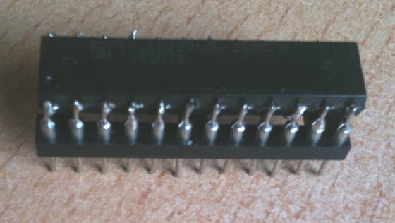
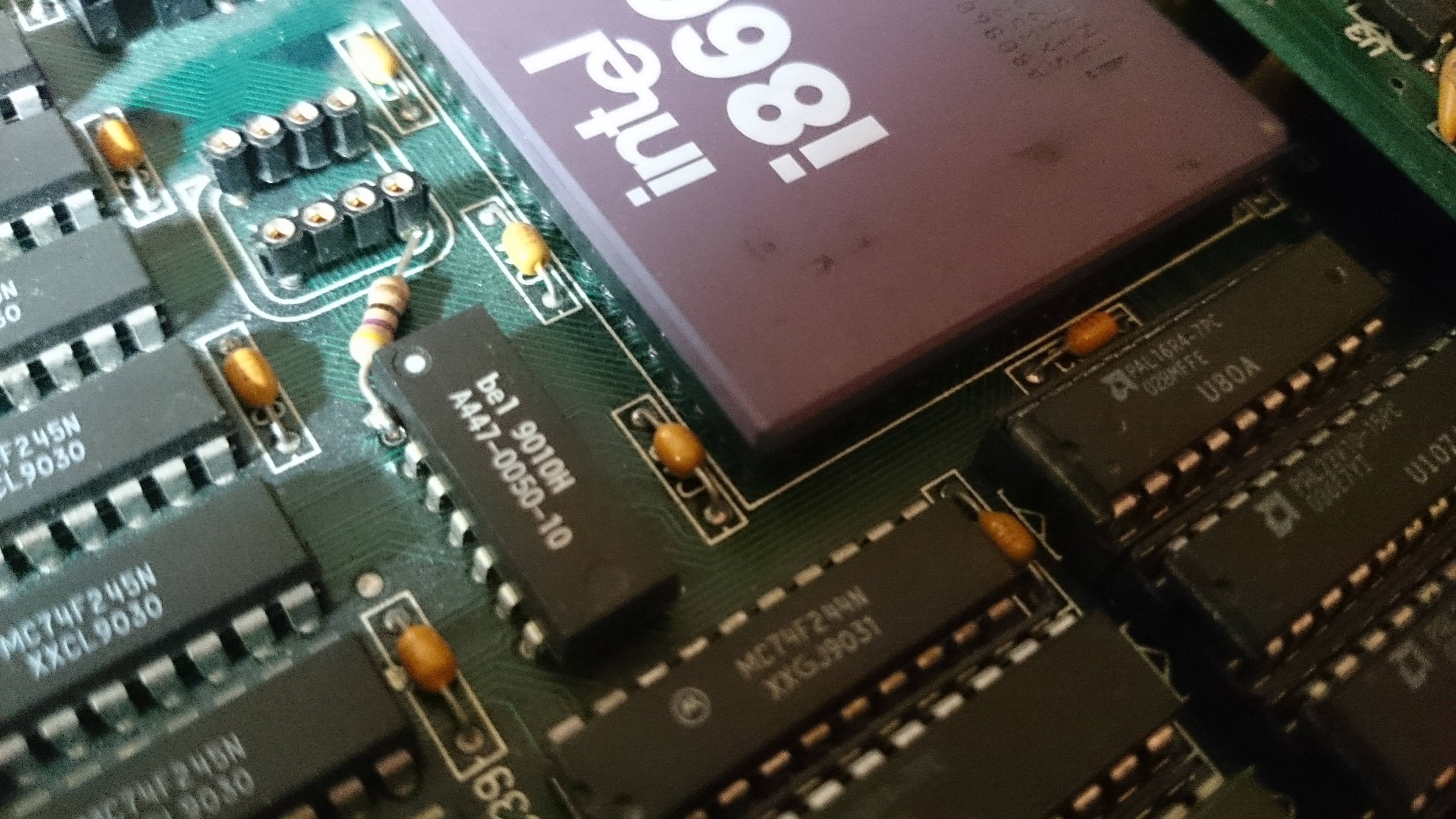
The most obvious fix the V1.2 had was a 47ohm resistor fitted between one pin of the 40MHz oscillator and pin-1 of an IC called “A447-0050-10 “. That’s a “10 tap leading edge delay module” made by Bel Fuse Inc.. Pin 1 takes the input signal and each other pin adds a delay of 5ns.
So I assume this fix was meant to reduce noise on the delay chip input to make its output cleaner.
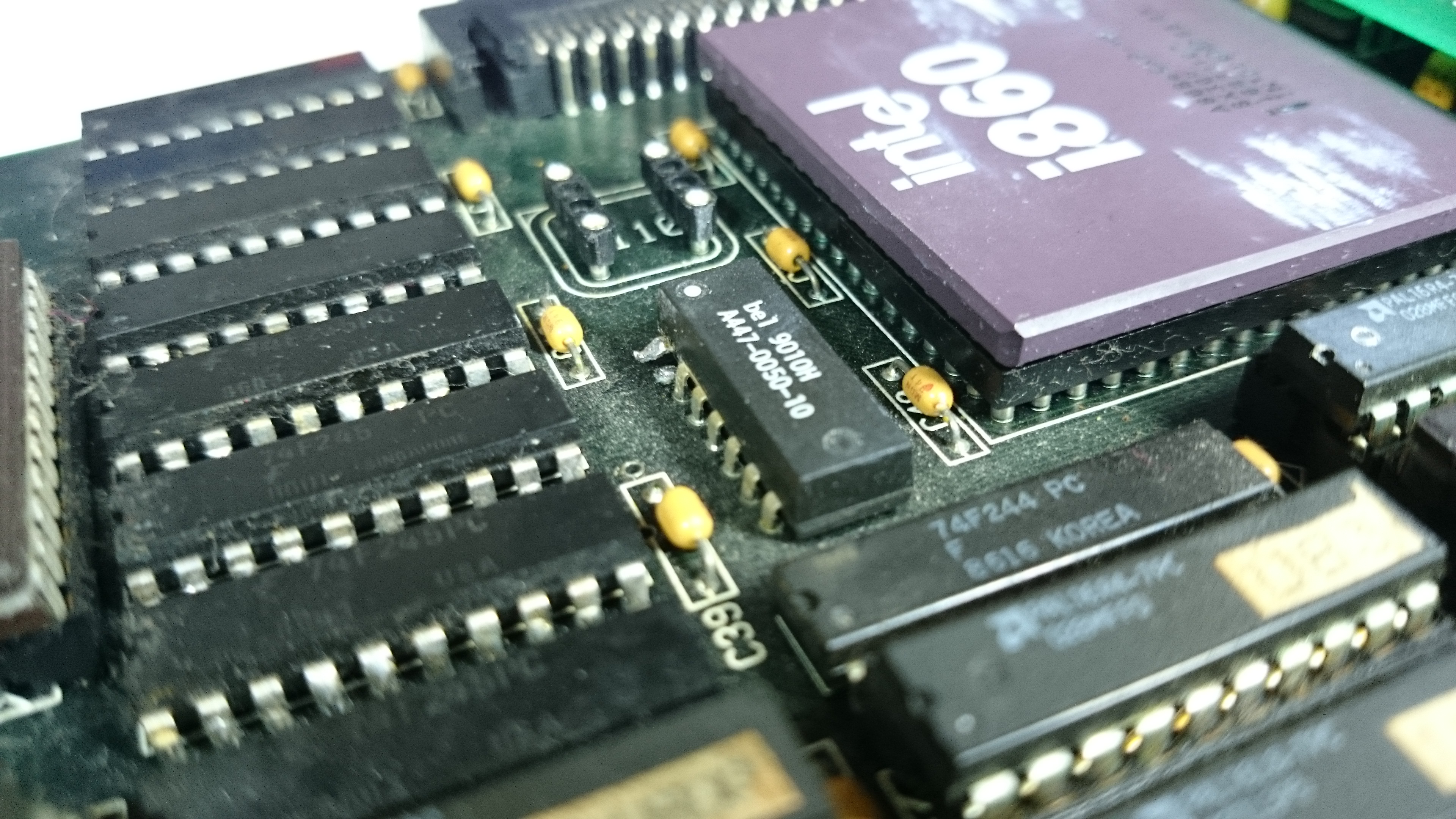
Anyhoo, here’s the quick and easy howto. The below picture shows the section of a NumberCruncher V1.1. near the almighty i860. Next to it is the (now empty) socket for the 40MHz oscillator. Next to that you see the 10-pin delay chip which pin-1 already had been cut and slightly bent upwards.
We need a bit of pin-1s leg so when cutting it, be sure to cut it as close to the board as possible!
Now for the next step. Get a 47ohm resistor and shorten its wires to bridge the space between the bent leg of the delay chip and the output pin of the oscillator (see below picture).
To make things perfectly clean, remove the pin remains by flipping the NS860 over and pull the remains with your solder iron and tweezers.
Step 2
I thought this would be a simple fix, too. There are some retrofitted jumper-wires on the back of the NumberSmasher near the ISA connectors.
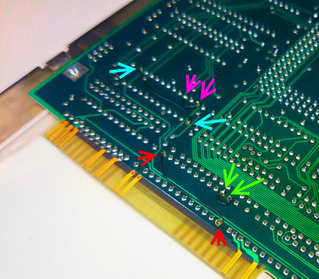 I’ve color adjusted the photo to make the wires more visible. Colored arrows show start and end of each wire
But taking a look at the chips those jumper-wires are connected, it showed that the two PAL22V10 of the V1.1 board were replaced by two PALCE610H – which is a completely different beast, same number of pins, everything else varies:
| max in | max out | macrocells | Specials | |
| PAL22V10 | 22 | 20 | 10 | |
| PALCE610H | 20 | 16 | 16 | D, T, J-K or S-R Flip_Flops, counters and large state machines possible |
Additionally here’s a side-by-side of the pinouts. This immediately explains the two long jump-wires from pin-1 to pin-13 (red & blue arrows) which connect the two clock inputs.
Here’s the PALCE610 in place:
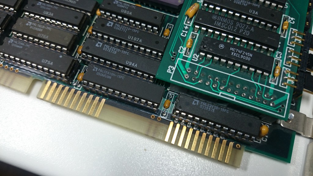 It’s the one at the bottom in the middle (named U93) and one hidden beneath the link-interface board (U-88).
My assumption is, that the PALCE610 has a completely different programming and the jump-wires just support the changes made, i.e routing the outputs of pin3 to input pin2 (green) respectively pin4 to pin 2 (pink) .
Next up: I will get out my Über-Programmer and try reading it – but I have low hopes, as MicroWay normally set the protection fuse on all the GALs/PALs they used.
Update
Wow, that was unexpected. Both PALCE610 hadn’t had the protection fuse set – at least on my retro-fitted V1.1 board. So lo-and-behold, here are the JEDEC files for you to program your own PALCEs! And because I couldn’t resist, I’ve disassembled the JEDs and added the PALASM code in the archive, too 😀
That said… it’s completely unclear what had been changed from V1.1 to V1.2 (well, U93 being close to the ISA connector gives a hint) and under which circumstances an upgrade is necessary at all.
But if you own a 1.1 and it behaves strange, you should give it a try.
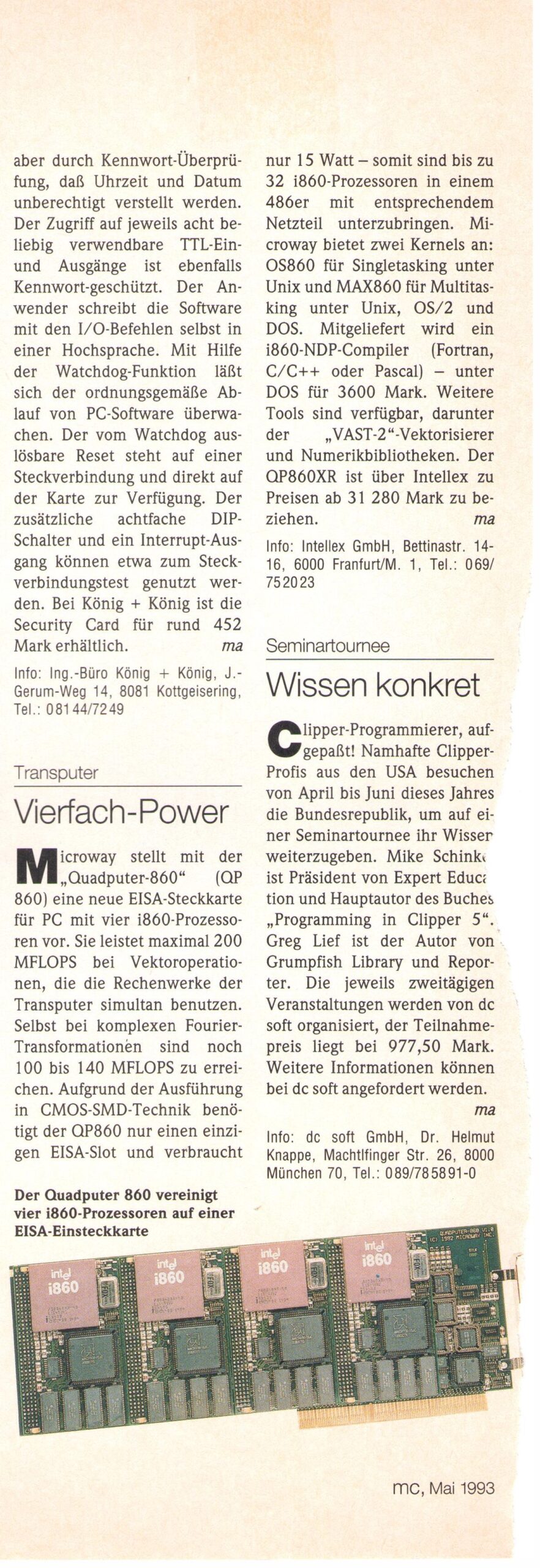
Nostalgia
After the NumberSmasher, MicroWay presented the “QuadPuter”, an EISA-Bus based quad-i860 monster… which had a short lifespan and was, well, expensive as expected. 31000 German Marks was exactly what you would have payed for an Volkswagen Golf mkII GTI 16V back then… one of the hottest hot-hatches you could get.
I found this snippet in one of my (German) computer magazines (“MC”, 1993) – they mention the OS860 (for DOS) as well as the MAX860 multiuser-OS for UNIX, OS/2 and DOS: