The usual source provides the full manual/documentation… down to the GAL equations.
All these enhancements enabled the B008 to create simple, yet powerful Transputer networks on a single expansion card and still makes it the perfect platform for todays Transputer retro experiments/fiddlings.
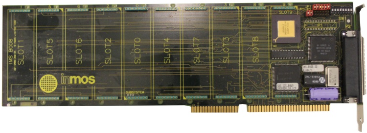
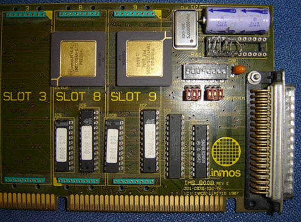
Here’s a late “Rev.F” version of the IMSB008:
The previous revision E had a ceramic version of the T2xx and used GALs instead of the CPLD you can stop in aboves picture.
Clones
Obviously the Inmos B008 had clones as the B004 did.
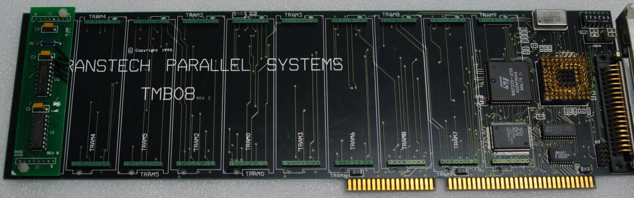
Transtech TMB08
Well, I guess there’s nothing which Transtech did not clone and/or improve…
In this case they used a AMD MACH CPLD from the beginning, a PLCC version of the T225 and everything else was SMD.
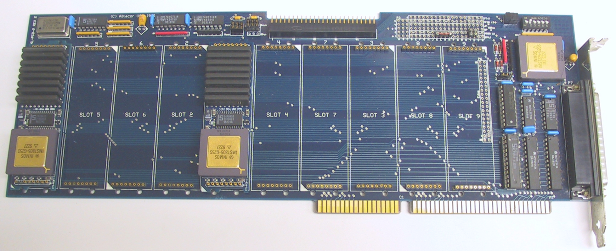
Alta SuperLink/XL Transputer PC Card
Alta Technology was a spin-off of Computer System Architects (CSA).
The SuperLink/XL board used TRAM modules like the Inmos B008, but featured a 20 MHz IMST225 Transputer to handle external interfacing and a beefed-up host interface design. Like the B008 it supported 10 TRAM’s
ARADEX
One of my first TRAMs was an ARADEX one, so this is a first for me, too. Actually I wasn’t aware that ARADEX also made TRAM carriers… but they seem to do quite some:
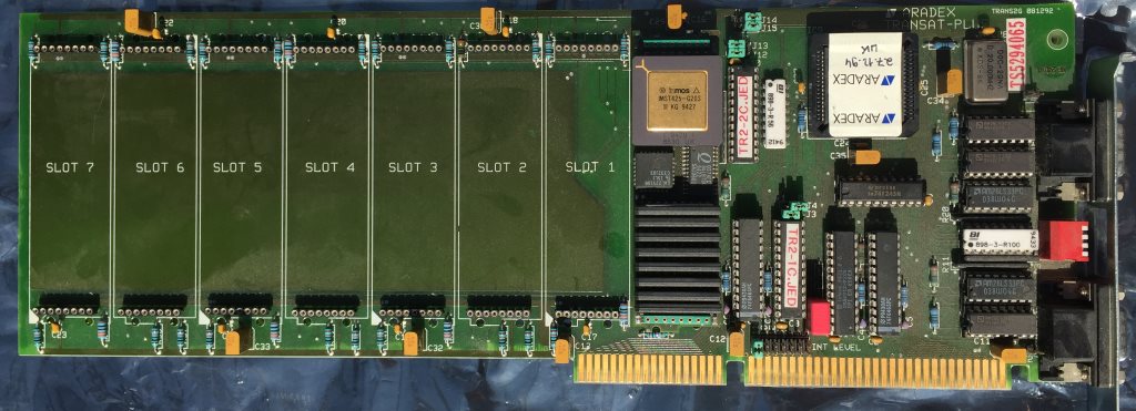
TransAT Plus
Their interpretation of the B008 theme features just 8 TRAM slots (vs. the 10 “standard”) which are strangely enough sorted in ascending order (0-7) and not like the B008 order of 1, 5, 6, 2, 0, 4, 7, 3, 8, 9. Also the TransAT provides two 9pin D-subminiature connectors in contrast to the B008s 37pin connector – most likely its layout is the so called Aalener Link-Interface. That includes the RS-422 differential drivers and receivers next to the connector (AM26LS23’s and AM26LS33’s).
Concerning other parts, besides an C012 they used some sort of CPLD – presumably to control the 16 bit bus – in the photos I have, I can clearly see the traces coming form the ISA Bus’ D[8-15].
It also uses the IRQs 10-12.
Last fun bit: They named the two GALs with their JED filenames. Very handy 😉
TransAT-8
The “8” in its name makes it a valid member of this collection – but it misses an C004 and also has just 8 TRAM slots… so maybe it should be considered somewhere between an IMSB004 and B008?
This time TIs 74ALS192/193 differential drivers are used, the PLCC chip is yet unknown… and in this case, a TTL chip (next to the ISA slot) is missing… all in all, it looks like a refresh of the TransAT Plus to me.
I even have a piccy of the back-side. Why the heck is somebody putting a GAL there?
It’s an open secret that the CSA mandelbrot benchmark tool (available in my ‘basic Transputer tools‘ package) is one of my favorite benchmark and test-tool when playing around with my various Transputer toys.
One fine day I thought VGA with more than 16 colo(u)rs would be nice… and the coding began. First step: Put the original source (well, already enhanced by a timer and some debugging) on github.
The original CSA Mandel program uses the official 640×480 16 color VGA mode (aka 0x12) and uses its own calls for that, i.e. no external 3rd party libs. Very manly 😉 but not very colorful…
So I created the first branch (aka Mandel_3) added a more “modern” command-line options handling and dived into hand-coding VBE (VESA BIOS Extensions) matters. That was very instructive and fun… and the first results showed that I didn’t just got 256 colors now but draw speed was increased, too 😯
Look Mom! More colors:
Running in host-mode (/t) on my P200MMX the initial screen took 6.6s vs 7.1s for 16-colors – so a difference of 0.5s or 7% should be much higher on Transputers, so I thought. And should this mean that bigger Transputer farms had been bottleneck’ed by the actual plotting of pixels?
Because 256 colors and higher resolutions (up to 1280×1024 depending on your VGA cards VESA BIOS) are fine, but even more colors are better, I branched the code a 2nd time (MANDEL_BGI) and replaced the VBE code by a BGI SVGA interface.
While originally Borland only supports VGA, there are 2 BGI drivers written by 3rd party developers which do support SVGA and up to 24-bit colors.
It’s commonly known that BGI is not the fastest graphics interface on planet earth… and the benchmark proved this:
P200MMX
Orig
VESA
SVGA
SVGA256
1
7.123
6.623
8.911
6.915
2
38.258
36.635
39.717
37.725
I was hoping the change would have more impact when running the same on my Cube system… well it didn’t:
65x T800 (integer)
Orig
VESA
SVGA
SVGA256
1
2.323
2.288
3.940
2.383
2
8.163
8.173
8.181
8.164
So as final conclusion, I will stay with the VBE SVGA drivers included in the V3.x code – it’s a good compromise between overall code/distribution size, comfort and speed.
The original VGA mode (0x12) will stay in the code forever to get comparable benchmark measurements – if you really need CGA/EGA/Hercules, you can always use the 2.x version.
Meet The Cube – this is the Transputer Power-House successor to the Tower of Power, which was a bit of a hacked frame-case and based on somewhat non-standard TRAM carriers with a max. capacity of just 24 size-1 TRAMs…
The Cube hardware
This time I went for something slightly bigger 😎 …A clear bow towards the Parsytec GigaCube within a GigaCluster. The Cube uses genuine INMOS B012 double-hight Euro-card carriers, giving home to 16 size-1 TRAMs – Parsytec would call this a cluster and so will I.
Currently The Cube uses 4 clusters, making a perfect cube of 4x4x4 Transputers… 64 in total. Wooo-hooo, this seems to be the biggest Transputer network running on this planet (to my knowledge)
If not, there still room left for more 😯
Just to give you a quick preview, this is what ispy responds when ran against the Cube:
32 x T800@20MHz/1MB (mainly TRAMs from MSC and ARADEX)
-> 96MB of total RAM
-> 70-130 MFLOPS (single precision)
~800MIPS combined integer power
~60Amps @5V needed (That’s 300W 😯 )
So we’re talking about 70-130 MFLOPS here – depending which documentation you trust and what language (OCCAM vs. Fortran) and/or OS you’re using. That was quite a powerhouse back in 1990 (Cray XM-P class!)… and dwarfed by a simple Pentium III some years later 😉
Just for to give you an comparison with recent hardware (Linpack MFlops):
Raspberry Pi Model B+ (700 MHz)
~40 DP Mflops
Raspberry Pi 2 Model B (1000 MHz – one core)
~134 DP Mflops
Raspberry Pi 3 Model B (1200 MHz – one core)
~176 DP Mflops
Short break for contemplation about getting old…
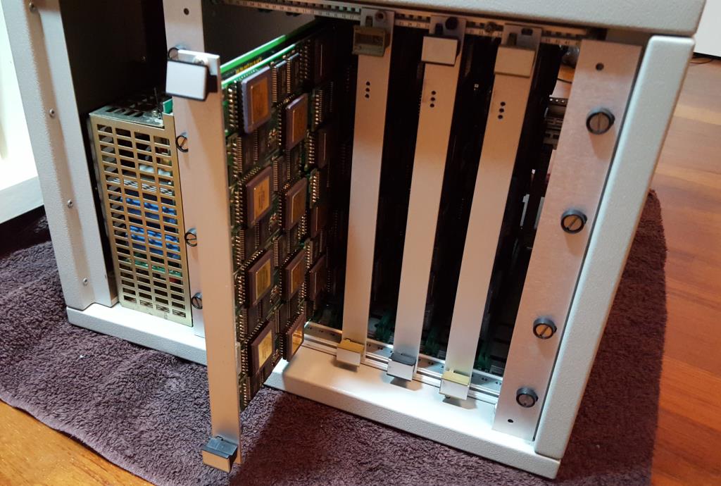
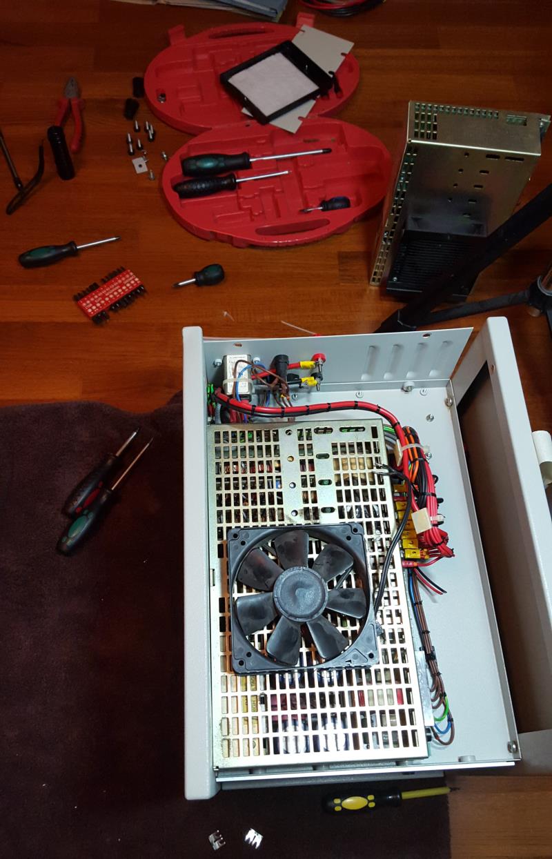
Ok, let’s go on… you want to see it. Here it is – the front, one card/cluster pulled, 3 still in. On the left the mighty ol’ 60A power supply:
Well, this is the evaluation version in a standard case, i.e. this is meant for testing and improving. I’m planning for a somehow cooler and more stylish case for the final version (read: Blinkenlights etc.).
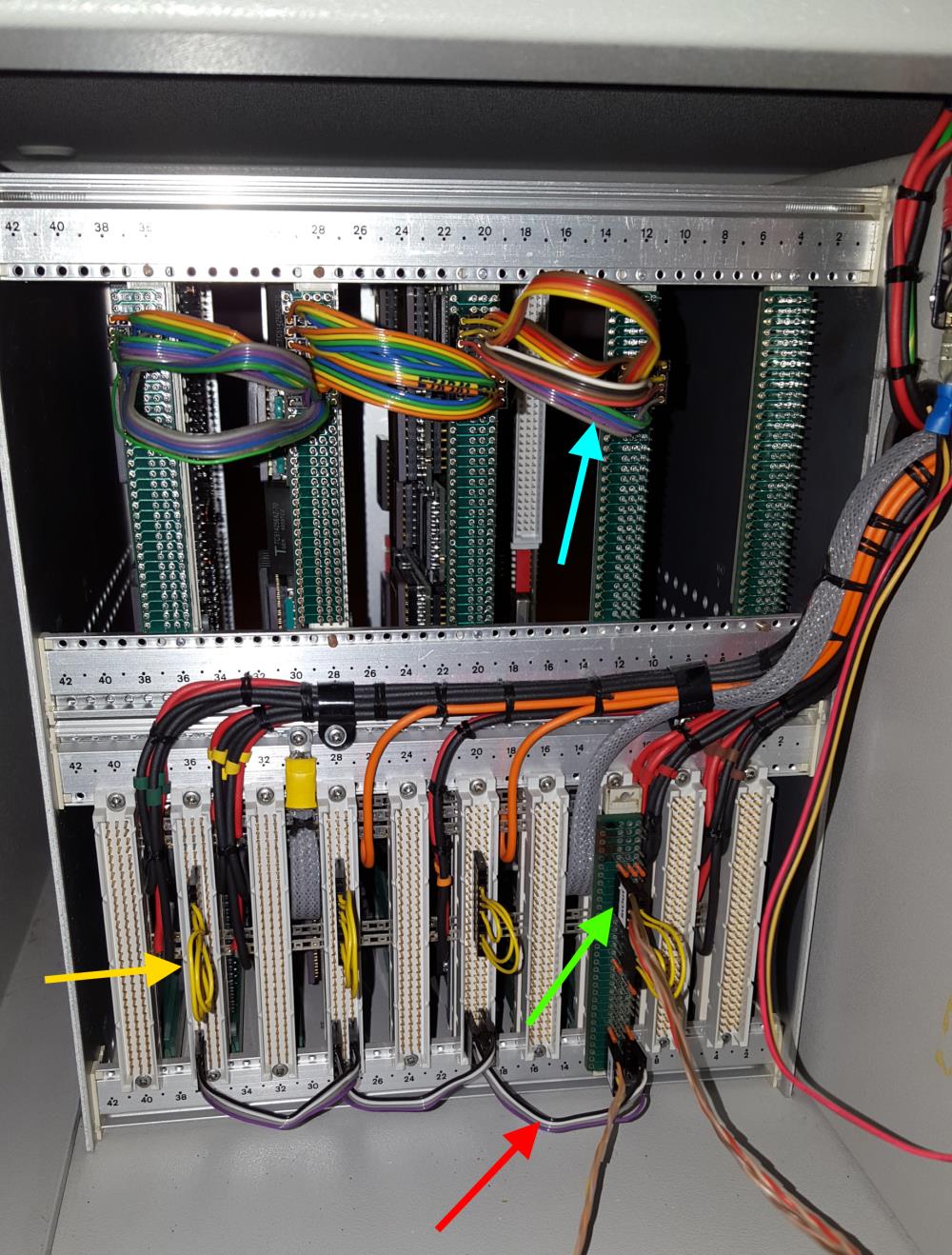
And here’s the IMHO more interesting view… the backside. It shows the typical INMOS cabling.
As usual, I color coded some of the cables.
The greenarrow points to the uplink to the host system to which The Cube is connected to. Red are the daisy-chained Analyse/Reset/Error (ARE) signals. The yellow so-called jumper-cables connect some of the IMSB004 links back into the boards network. And in the upper row (blue) four ‘edge-links’ of each board are connected to its neighbor.
This setup connects four 4×4 matrices (using my C004 dummies as discussed here) into a big 4×16 matrix. Finally I will ‘wrap’ that matrix into a torus. Yeah, there might be more clever topologies, but for now I’m fine with this.
Building up power
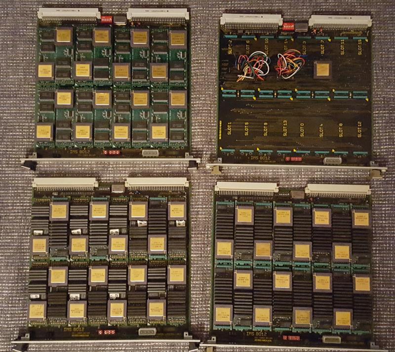
For completeness, here’s a quick look at how things came together.
The 4 carriers/clusters with lots of size-1 TRAMs… upper right one is the C004-dummy test board (now also fully populated). Upper left is pure AM-B404 love <3
Fixing/replacing the broken power-supply (in the back), including the somewhat difficult search for a working cooling solution:
The Cube software
Well there isn’t any specific software needed to run The Cube, but it definitely cries out loud for some heavily multi-threaded stuff.
So the first thing has definitely to be a Mandelbrot zoom. As usual, I used my very own version with a high-precision timer, available in my Transputer Toolkit.
Here’s the quick run in real-time – you can still figure out visually each Transputer delivering its result:
So this is running fine – using internal RAM only. On the other hand, it seems that the current power supply has some issues with, well, the electric current.
When booting Helios onto all 64/65 Transputers which uses all of the external RAM, very soon some of them do crash or go into a constant reboot-loop.
By just reducing the network definition (i.e. not pulling any Transputers) to 48, Helios boots and runs rock-solid.
Because measuring the voltage during a 64-T boot shows a solid 5.08V on all TRAM-slots it most likely means the power supply either can’t deliver the needed amount of Amps (~60) or produces noise etc. 😥
So this is the next construction site I have to tackle.
As soon you’re talking about Transputers with people which weren’t there back in 1985 you’ll be asked this very soon: “How fast are these Transputer thingies”? Then there’s a stakkato of “MIPS? Whetstones? Dhrystones?” etc…
As always with benchmarks, the only valid answer is “it depends”. Concerning Transputers that’s even more true.
First, I suggest you read this Lies, Damn lies and benchmarks document from INMOS itself. It pretty much describes the dilemma and all the smoke and mirrors around that matter.
Benchmarks? It depends.
So you’ve read the above INMOS document? As you might saw, it’s full of OCCAM code. That’s the #1 prerequisite to get fast, competitive code (as long you’re not into Transputer assembler). From there it gets worse if you use a C compiler or even FORTRAN…
My little benchmark
Because it scales so well, works with integer as well as floating point CPUs and also runs on the x86 host while using at least the same graphic output routines, my personal benchmark is CSAs Mandelbrot tool (DOS only).
My slightly modified version is part of my Transputer Toolkit, which is downloadable here. You will need that version because I extended the code of this Mandelzoom with a high precision timer (TCHRT, shareware, can’t remove the splashscreen, sorry) when run with the “-a” parameter. You’ll need my provided default “MAN.DAT” file, which contains 2 coordinates to calculate (1st & 2nd run) to get comparable numbers.
So to bench your Transputer system start it with:
man -v -a
which runs it in VGA mode (640x480x16c), loads the coordinates from “MAN.DAT” and when done presents you with a summary screen like this:
To run it on your hosts x86 CPU, call it with “man -t -v -a”
The Results
Here are my results of the different Mandelzoon runs I made in the past. The blue background marks the host machine results, yellow are the integer timings and green is where the mucho macho things are happening.. well, sort of 😉
There are two columns for the results, the HD timer and the hand-timed runtimes. This is because these are from days before I enhanced the Mandelzoom.
This table will continously updated of course. e.g. the last row is pretty new – what might that system be? 😯
The sources are available in my github repository – so we can collaborate on enhancing and optimizing it.
HD in-programm Timer (s)
Hand-Timed
System
1st
2nd
1st run
2nd run
Comment
i386DX/33 (0kb L2)
1800
0
1:30:00
(canceled)
0
Canceled 1st run after a quarter of Mandelbrot was done…
i386DX/33 (0kb L2) + 387
588
3316
0:09:48
0:55:16
Am386/40 (0kb L2) + 387
490
2980
0:08:10
0:49:40
21% faster clock but only 10.5% better result
i386DX/33 (128k L2) + 387
274
1547
0:04:34
0:25:47
Am386DX/40 (128k L2) + 387
228
1292
0:03:48
0:21:32
i486DX/33 (8k L1, 0k L2)
01:06.24
368.56
Pretty close to a single T800-20
i486DX2/66 (8k L1, 128k L2)
00:33.72
185.51
Very close to 2x T800-20
Pentium 133 (256kb L2)
00:09.09
00:55.01
About 8x T800-20
Pentium 200 MMX
00:07.13
00:38.06
About 9x T800-20
AMD K6-3+/266
00:06.00
00:32.00
Downclocked, 64k L1, 256kb L2, 1M L3
Core i3-2120 3.3GHz
00:01.66
00:02.13
VirtualBox,1 CPU
1x T425-20
0:00:25
0:02:28
There’s something wrong here – needs re-run
2x T425-20
00:51.55
04:56.60
3x T425-20
00:34.42
03:17.81
4x T425-20
00:25.86
02:28.56
5x T425-20
00:20.74
01:58.96
6x T425-20
00:17.37
01:39.19
9x T425-20
11
62
0:00:11
0:01:02
13x T425-20
8
42
0:00:08
0:00:42
21x T425-20
5
27
0:00:05
0:00:27
25x T425-20
4
23
0:00:04
0:00:23
65xT425 (48x25Mhz, 16x20MHz)
00:02.323
00:08.163
Actually it was 64xT800 and one T425 forcing the calculation to integer
1x T800-20
01:09.13
06:27.18
1x T800-25
0:00:55
0:05:09
25% higher clockrate should result in 17.5% speedup. Incl comm-overhead that pretty much fits
1x T800-30
00:00.46
00:04.30
2x T800-20
00:35.65
03:13.79
3x T800-20
00:23.16
02:09.32
4x T800-20
00:17.43
01:37.04
5x T800-20
00:14.04
01:17.74
6x T800-20
00:11.82
01:04.83
5x T800-25
11
62
0:00:11
0:01:02
9x T800-20
8
40
0:00:08
0:00:40
13x T800-20
5
30
0:00:05
0:00:30
17x T800-25
00:03.8
00:18.59
“1st run” shows that the slow ISA interface is really getting a bottleneck
This is the collection of other Transputer interfaces and cards (i.e. not from the usual suspects) I came by here and there. And no, I don’t actually own them all.
Some are rare, some are odd, may are cool and most are all three of them 😉
This post will be irregularly updated as new finds come along…
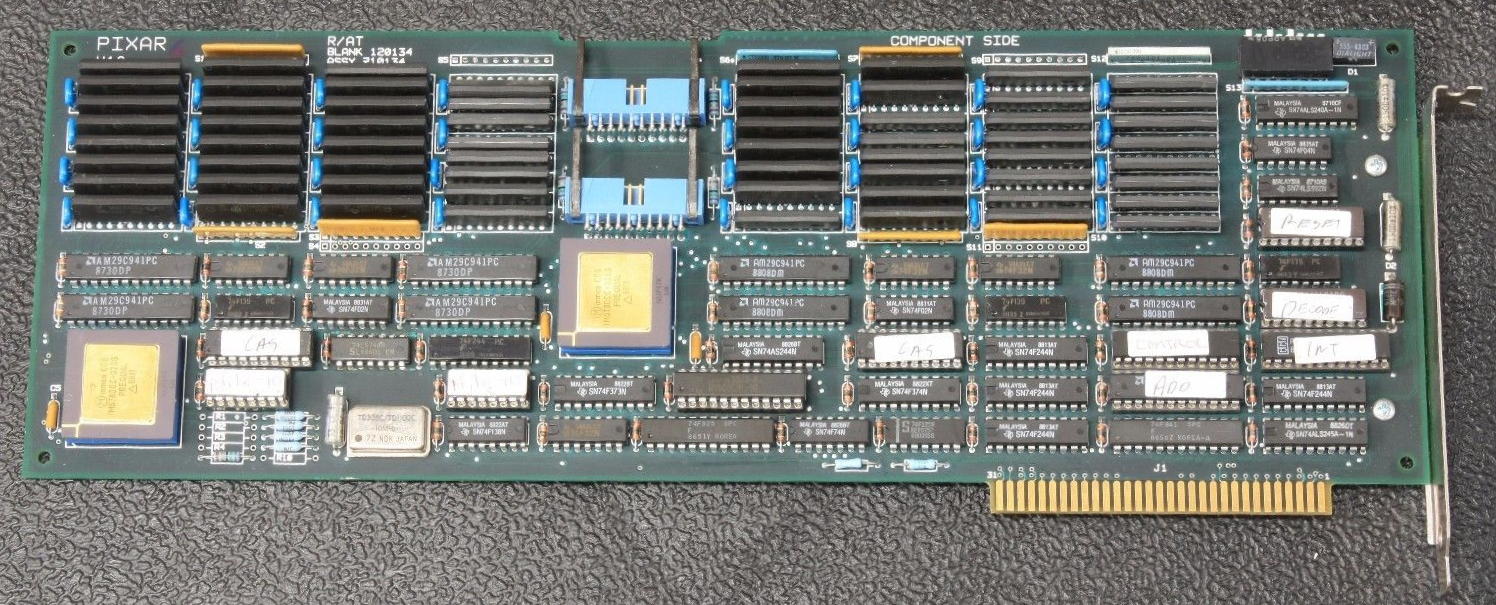
Pixar Transputer Card
Yes, that’s true. Pixar built its own Transputer interface back in the days, simply called “Render Accelerator”. Nomen es omen 😉
In constant search of raw computing power they tried out everything, eg. Intels i860 and others. It was just another logical step to try speeding-up Pixars Renderman package by using a Transputer farm. As an early adopter, they had to build their own stuff to suit their demands. Here’s a very interesting read about the long way Renderman came from and which hardware they’re were using. This article about texturing techniques is mentioning this card on pp.16.
The mentioned Jeffrey Mock was also quite busy during his Pixar days in helping Logical Systems (LSC) by writing a concurrency library for their C-Compiler.
Here’s the front of the full-size 8bit ISA card – filled up to the brim.
It features two T800-20 Transputers, each having its own 4MB of RAM. Two links are facing the outside-world – I presume it’s been meant like a up- and down-link to the next card.
The rest is standard early-days ISA bus, C012, Transputer DRAM design.
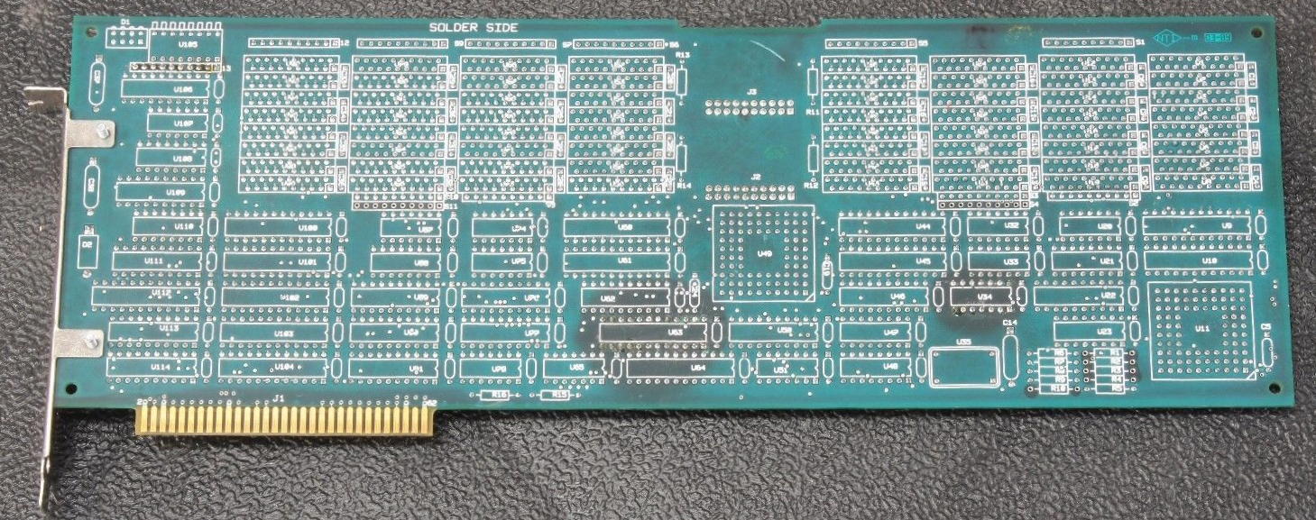
No much to say about the back side. The silkscreen is a bit uncommon, but it’s nice when it comes down to repairing… and some “burning” shows, that seemed to be the case with this specific card.
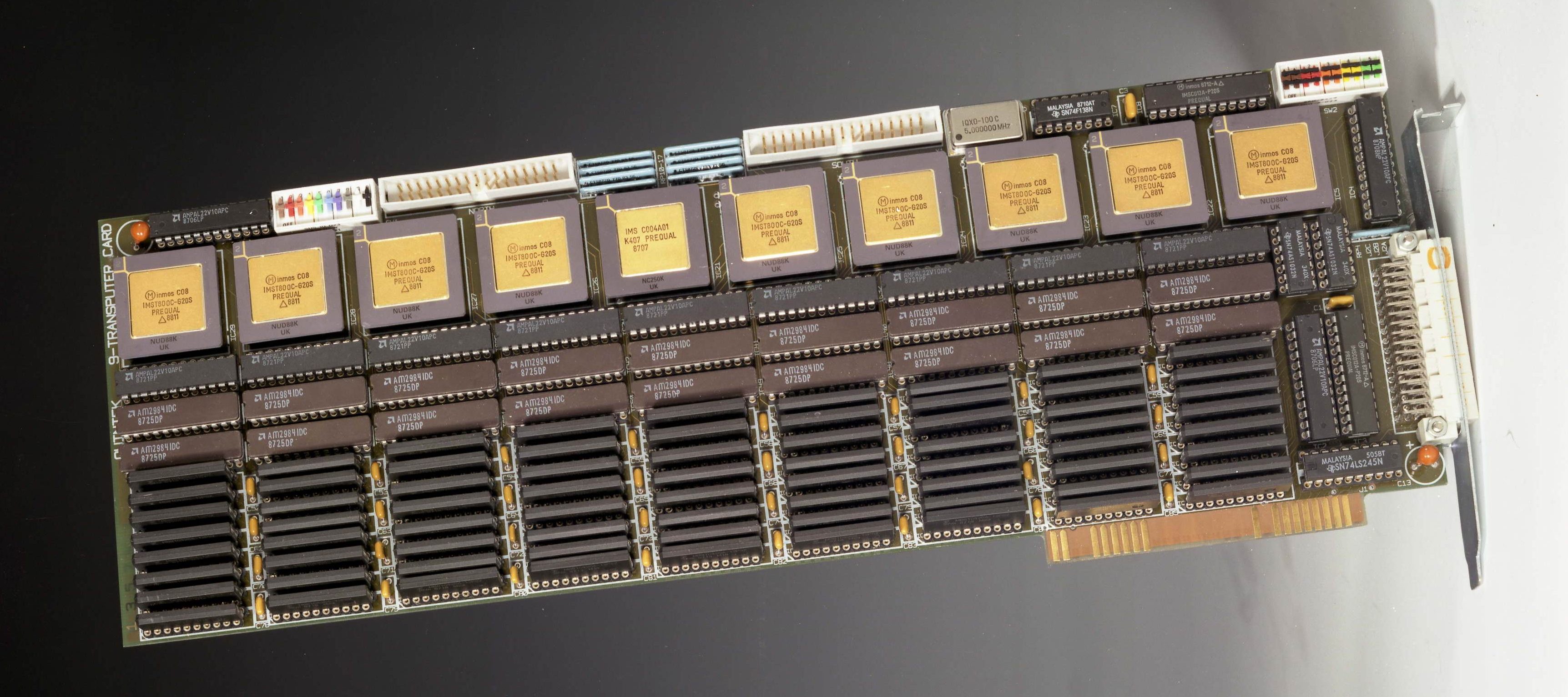
The Quintek T9
This is a very manly approach into transputing matters… don’t give me that step-by-step upgrading of an Transputer array. Just do it once and do it right 😉
Yes, that’s 9 Transputers, each with 1 or 4MB RAM and a C004 all directly soldered onto that 8-bit ISA card. It sure was expensive…
While there’s a C004 (the 6th golden IC from left), there’s no T2xx to control it. So I assume that one of the T800 is in charge to configure it… or this is done through the ISA link-interface as there are two C012 on the card,
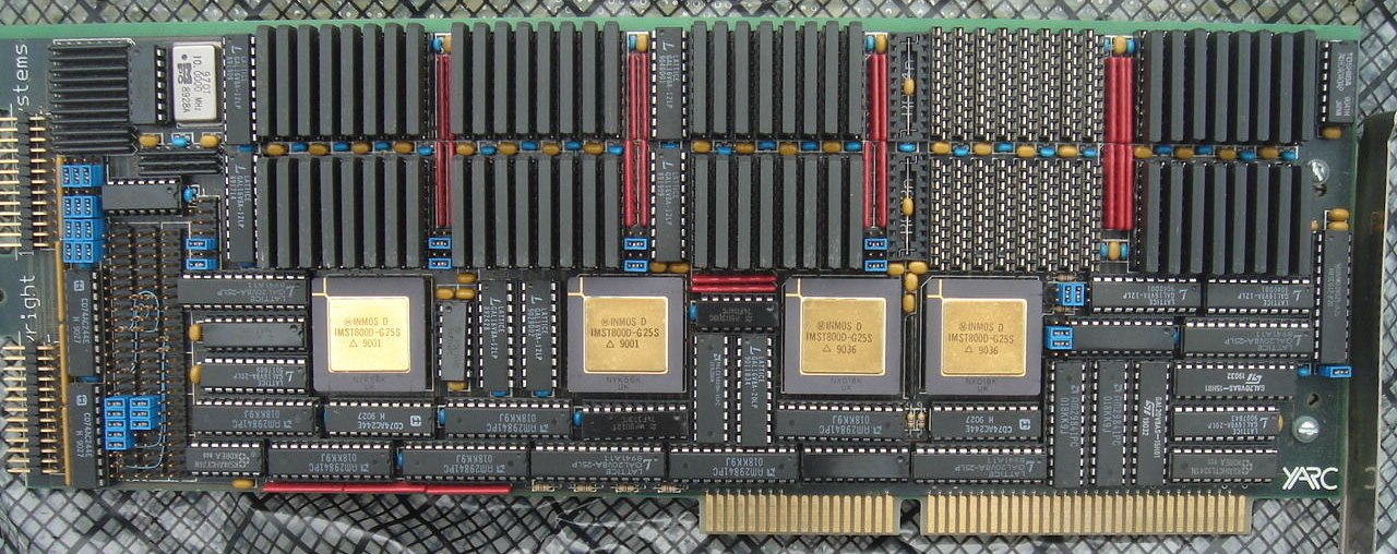
The YARC ProTran
This is a fullsize 16-bit ISA card from YARC. It features 4 Transputers with the option of supporting them with a (for the time) big amount of RAM.
The ProTran board can be equipped with 1 to 4 Transputers. The root Transputer (the rightmost) can have acces to 1-16 megabytes of RAM – it’s 8 in this picture. Each of the other three can be configured with 1 to 8 MB. That was very serious stuff back then.
What’s most interesting about this card is that YARC didn’t gave much about standards and went a proprietary route in many places:
A proprietary bus interface is said to provide a peak I/O speed exceeding 1 MB/sec
All links, event inputs and subsystem control signals are fed to a proprietary pin-field array.
The memory design uses a multibank and interleaving technologies to achieve zero wait state performance
All this explains the excessive use of GALs in the lower half of the card. Beside the proprietary approach the ProTran offered a compatibility mode (read: B004 interface) to use standard INMOS tools.
CSA
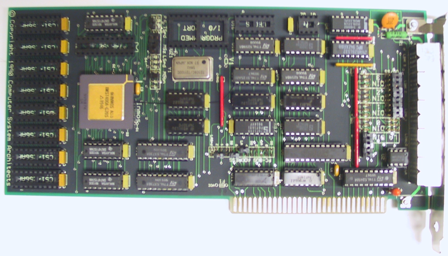
CSA (Computer Systems Architects) was big in the educational market and produced smaller, better integrated B004 compatible Transputer cards. The higher integration of DRAM parts allowed half-length ISA cards meant for evaluation or as a starting point for building bigger systems later. (The following pictures are courtesy “the PCPUTER” page. Permission to repost them were kindly granted)
Meet the “Transputer Kit PC Card” – They came bundled with a slightly restricted version of the Transputer Toolset, together with a great manual which described lots of different programming and hardware interfacing lab-type experiments. These cards used standard multi-pin circular DIN connectors/cables to route the link and reset signals, and provided the first hands-on introduction to distributed parallel processing for many people. They included a “budget” T400A 32 bit non-floating point processor, and off-processor memory was an option
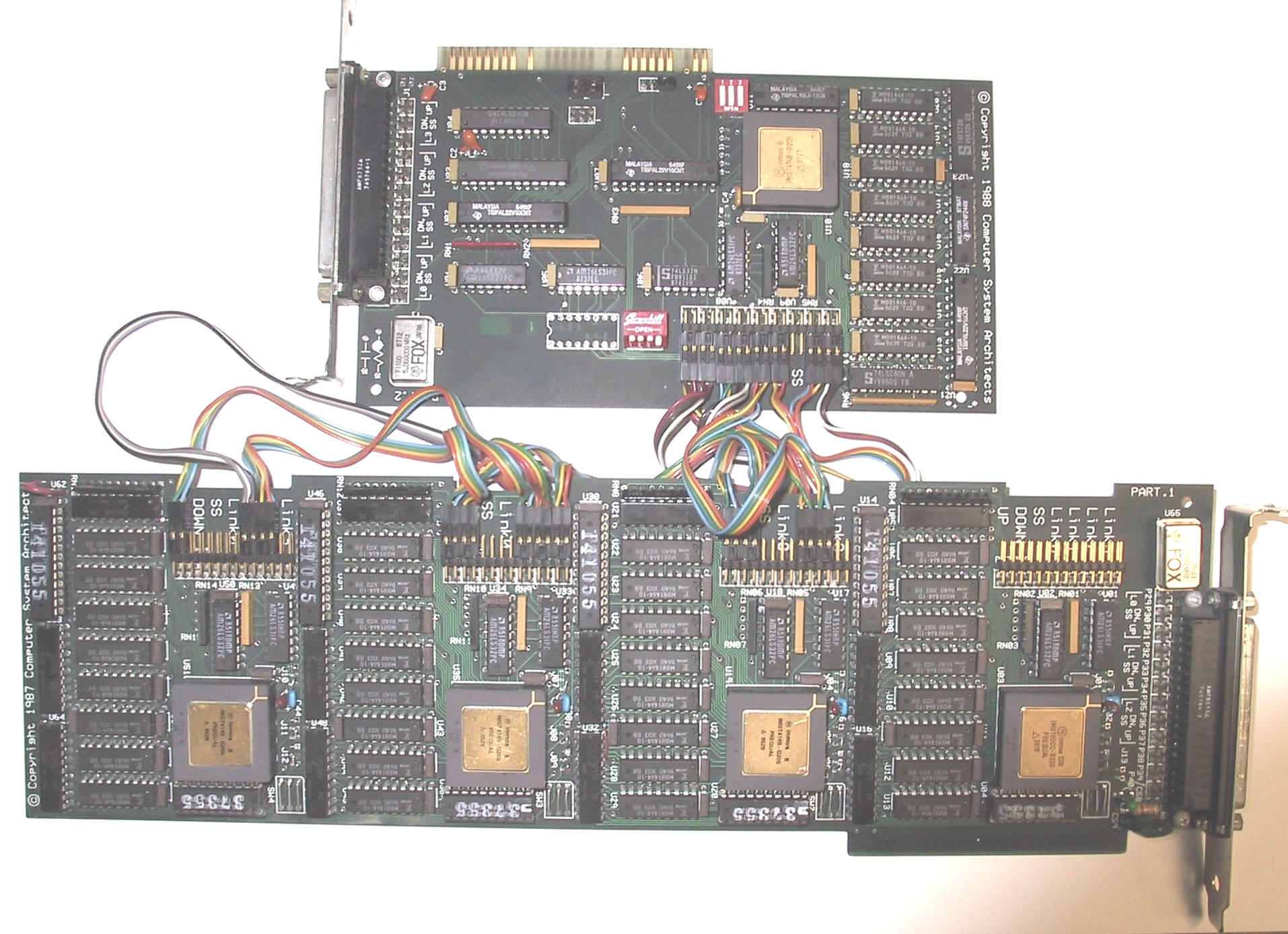
This is th PART.1 four processor board – mainly a carrier for CSAs proprietary Transputer Modules (like INMOS’ TRAMs), and the single processor PART.2 board featuring a PC interface.
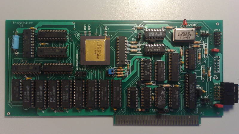
The “Gerlach card”
The card from the book “Das Transputerbuch” from A. Gerlach is a typical example. It has its own post on this page.<
Very simple design but only 2 layers and completely documented in the book.
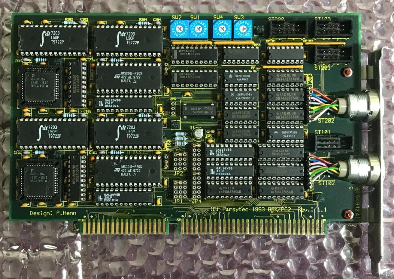
Parsytec BBK PC-2
As ususal, Parsytec did things a bit different than most others.
Their ISA interface “BBK PC-2” has two RS422 interfaces using their ‘standard’ Lemo connectors (see the the post about the x’plorer for more about these)
All Parsytec interfaces, no matter which bus-system were called BBK and having a number attached, telling you how many link interfaces were provided, e.g. the Sun SBUS card was called BBK-S4…
Like the HEMA card, this one has SRAM buffers, too. Also it looks like it’s using a 16-bit interface to the ISA bus.
Ingenieurbüro Ingo Mohnen (aka “IB Mohnen”)
This “engineering office” is pretty unknown in the already small Transputer community, even more outside Germany.
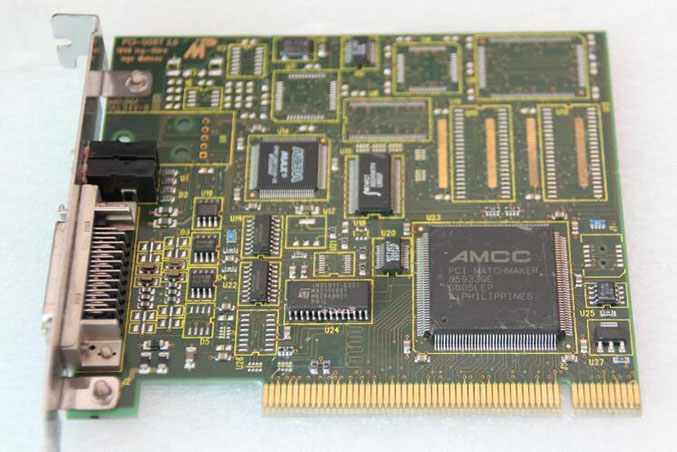
But they did very sophisticated Transputer interfaces. Actually they were the OEM for Parsytecs PCI BBK but offered other cards, too.
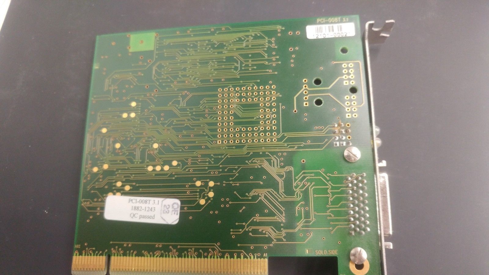
For example the PCI-008 series. Obviously a IMSB008 for the PCI bus. I have pictures of the V2.0:
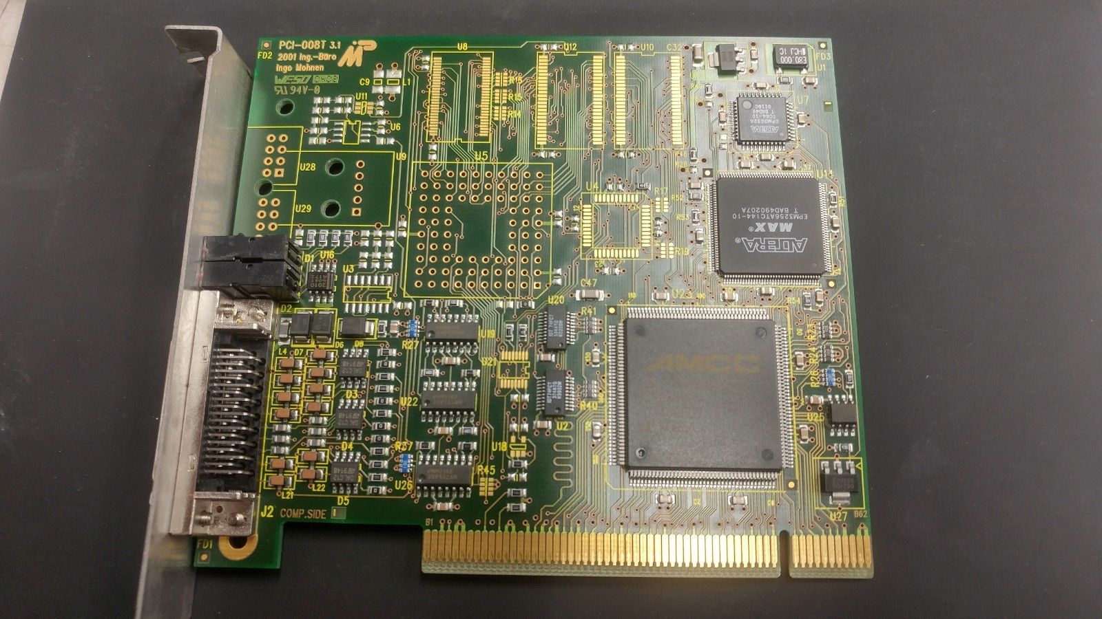
…and V3.1:
Both versions seem to be primarily meant as OS-Link interface, while they offer space for an onboard Transputer and RAM both weren’t populated with these.
V3.1 also seem to implement the C011 into the FPGA while switching back to a PGA Transputer while having used a TQFP package in version 2.
Then there was the already mentioned BBK line of cards. Starting with the BBK-PCI light of which I don’t have a better picture than Ram does on his page (Fun fact: Also Sundance OEM’ed this card from IB Mohnen). Basically it’s a IMSB004 compatible interface for PCI. Sweet, want one!
The bigger brother is the BBK-PCI, featuring 4 full blown OS-Links and acting as PCI bus-master. Definitely the high-end of PCI link-interfaces. I do own one of these but need to make some nice photos… so in the meantime use the link to Rams page 😉
The Hema TA2 is some very special specimen of ISA interface cards. IMHO it’s the last and most sophisticated interface you can run in an ISA bus. These are the feature highlights:
16 bit ISA interface
half-size card
4 TRAM sockets
TTL and RS422 link connectors (if RS422 drivers are fitted, TTL is not usable)
B004 compatible ‘Fast Mode’ as well as 100% vanilla ‘Slow Mode’
The TA2 implements an Idea which can be found in some documents from those days, about getting the maximum speed from the sluggish ISA bus and a link-interface chip like the IMS C011/012:
Overlapping acknowledge by using FIFO buffers and a controlling FPGA.
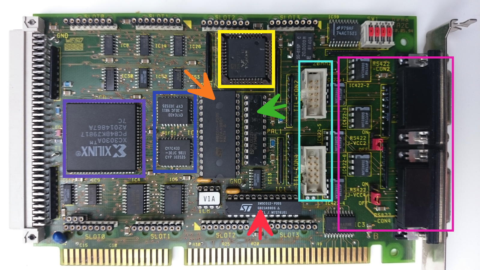
This is how the TA2 looks like:
I’ve marked the the important parts with colors/arrows:
red arrow – the IMS C012
orange arrow – the IMS C011 connected to
blue – two 1KB FIFOs controlled by
yellow – a MACH 110 CPLD and
green arrow – a PAL
purple – a XILINX 3030 FPGA doing the control logic
cyan & magenta – TTL and RS422 link connectors
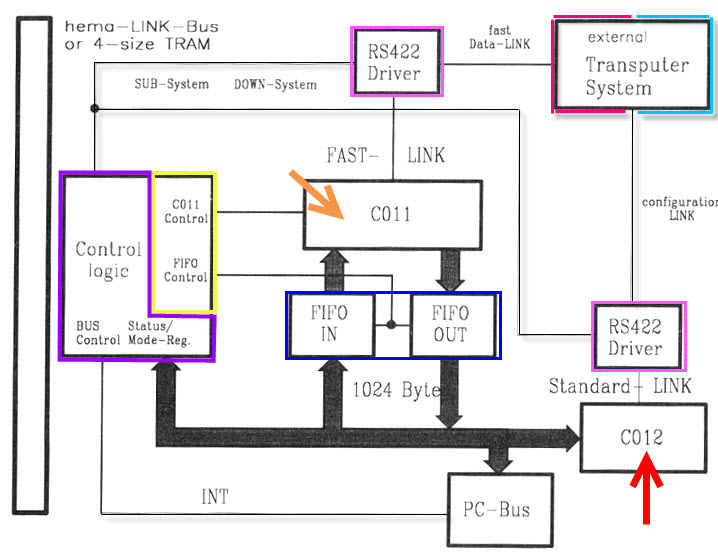
And here’s the block-schematic using the same colors:
The schematic also mentioned the two other cool features of the Hema TA2:
Four TRAM slots and the “hema LINK-Bus”, a proprietary two row DIN 41612 connector which provides all links/subsystem which were used otherwise by the 4 TRAMs.
Finally there is a 4-bit microswitch (upper right corner) to set a unique ID for the card so you can identify up to 16 cards in a single system.
Software
Using the provided control program “CTA2” everything can be set by software, e.g.
Base addresses for the fast- and slow link (0x150/0x158 by default)
Swapping fast/slow link configuration
Linkspeed for every link (fast/slow/TRAM/hema-bus)
Up- /Down-subsystem control
Interrupts per link
Waitstates
All the hardware wise ‘jumping through hoops’ still doesn’t do the job alone. To reach the ultimate ISA speed (the docs are talking about up to 1mbps) the communication needs to be tuned, too.
Lets talk a bit x86 assembler here (ahhhh), and DOS-only for sure:
It’s not enough to use simple in and out port instructions and constantly poll the C011/12 status register – that’s way too slow. You’ll need to go for the string variant(s) ins[b|w|d] combined with the rep instruction. Here’s an example for a C insb wapper function:
void insb(UINT16 port, void *buf, int count) { _ES = FP_SEG(buf); /* Buffer Segment */ _DI = FP_OFF(buf); /* Buffer Offset*/ _CX = count; /* Bytes to read*/ _DX = port;/* from Port xy */ asm REP INSB; }
Same goes for outs[b|w|d] respectively. But there’s another extra to care for: The TA2 provides special registers to give you deeper insight into its status, e.g. FiFo fill-rate (empty, half-full, full), FiFo interrupt settings.
So in effect, you couple the fast ins/outs instructions with interrupts attached to e.g. input half-full and output full.
That said, there are some caveats. ins[b|w] and outs[b|w] are supported from the i8018x and V20 on. insd and outsd needs a 386.
And then there are possible speed penalties with 32nit processors (i.e. 386 and up) as they optimized the port instructions for virtualization (Virtual 8088 mode, not todays VM!) resulting in 100+ cycles per call.
So when everything is 100% optimal, hema says in its documents these are the possible transfer speeds to reach:
Function/Array size
1K
10K
100K
1MB
Read FiFo
150kB/s
390kB/s
570kB/s
615kB/s
Read Polled
160kB/s
160kB/s
160kB/s
160kB/s
Read Direct
600kB/s
610kB/s
610kB/s
610kB/s
Write FiFo
565kB/s
600kB/s
610kB/s
610kB/s
Write Polled
160kB/s
160kB/s
160kB/s
160kB/s
Write Direct
610kB/s
610kB/s
610kB/s
610kB/s
FiFo – Using interrupts and syncing status of fill level.
Polled: Each byte is synchronized with the C012 status
Direct: Like FiFo but no syncing.
Well, this has to be proved yet. Seem I need to write a benchmark… someday 😉
I’d call the Inmos B004 the “mother of all Interface cards”, simply because it was the first ISA card sold by INMOS. And it wasn’t just the card but it also defined the (PC) standard of the software interface, mostly called the “B004-interface”. What a surprise 😉
So being the first card, it is quite big (full ISA length) while not offering really impressing specs: 8bit XT Bus, just one Transputer –TRAMs weren’t invented yet- and a max. of 2MB RAM (DILs). To do it justice, the manual rightfully calls it “Evaluation Board” and for that purpose it’s totally fine – remember that 2MB were quite an amount of RAM back in 1984.
To create a multi-Transputer network you had to either plug-in multiple B004s or connect an external network to the onboard connectors (the blue ones in the picture below).
As mentioned, the B004 software interface is what makes this card a keystone in the Transputer universe. All communication to the host (i.e. the XT/AT compatible PC) is done through a port range normally beginning at 0x150 (base, can be moved by some cards).
With certain offsets the host software can communicate with the Transputer, or the C011 to be precise:
Base Address
Register
Comment
+0x00
C011/12 input data
read
+0x01
C011/12 Output data
write
+0x02
C011/12 input status register
read = returns input status
write = set input interrupt on/off
+0x03
C011/12 Output status register
read = returns output status
write = set output interrupt on/off
+0x10
Reset/Error register
write: Reset Transputer & C011/12 and possibly subsystem (check manual)
read: Get Error status
+0x11
Analyse register
(un)set analyse
This mapping was used by more or less all ISA interface cards and extended by other more sophisticated interface cards later.
Clones
Needless to say, that very soon there were a couple of “inspired” models from other manufacturers. AFAIK all of them support Transputers up to 30MHz, which the B004 didn’t… so they’re actually better.
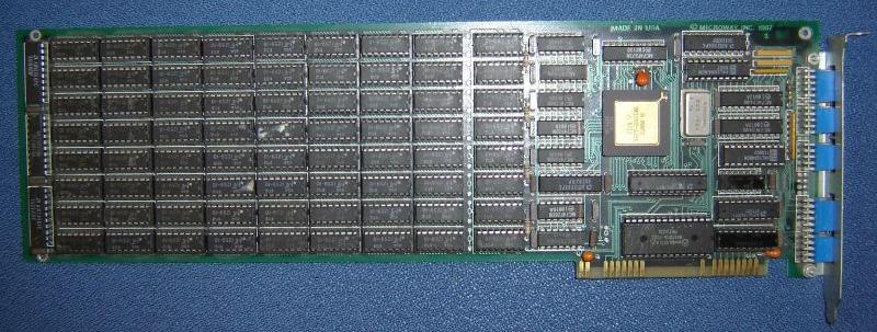
This example is from Microway (yes, those guys who later build the i860 Number Smasher), named Monoputer and dated 1987. Up to 2MB could be used on it. Mind the connectors being accessible from the outside:
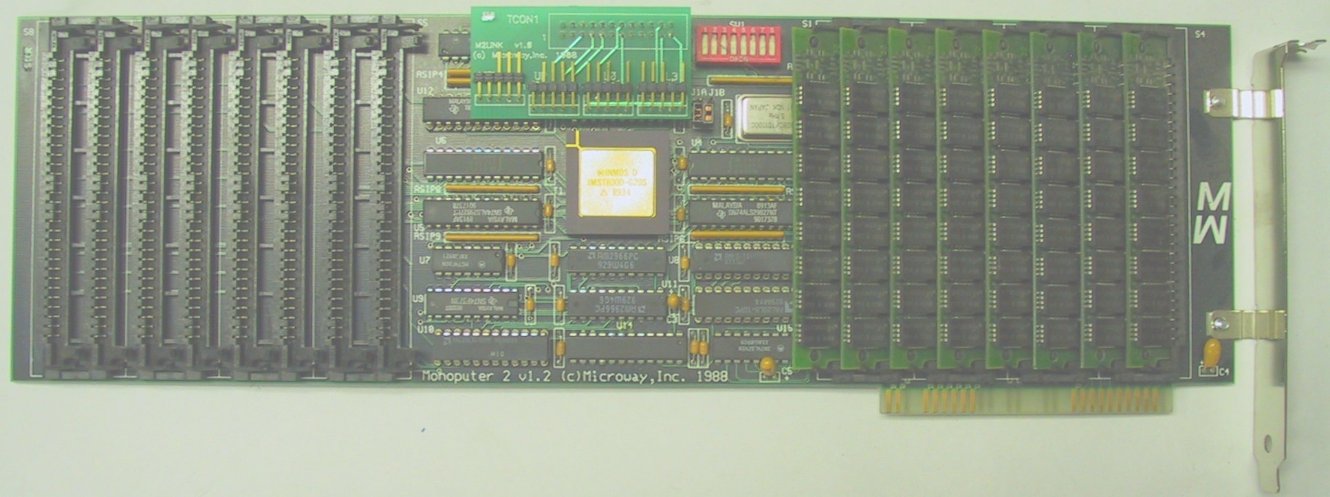
Later they produced the “Monoputer 2” which was more modern and used SIMM RAM modules instead of DIL parts. The Transputer and Linkinterface moved into the middle of the card and the link connectors were moved inside the pc case again – the connectors are the very same used on the NumberSmasher860:
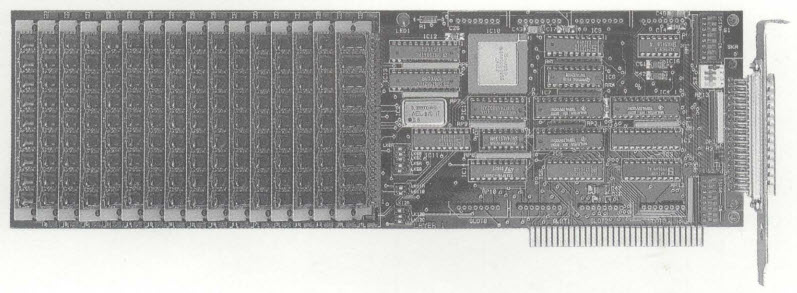
And here’s the one Transtech made, calling it TMB04 mind the SIMM banks which enable the card to give home up to 16MB RAM (at 3 cycle speed!):
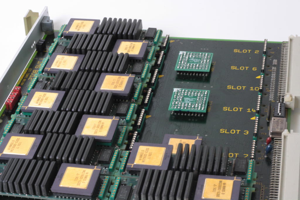
The IMSB012 is my favorite TRAM carrier board. Room for max. 16 (size-1) TRAMs and plenty of external connectors. The perfect platform to build a successor of the ‘Tower of Power’.
Like with all TRAM carriers having more than 8 slots, it was a good decision to put at least one C004 link-switch onto the board.
While that’s generally a good feature, you (and me) might not need the option to reconfigure your Transputer network several times a week… And if you’re completely sure how you like your network it would be better to set if once and for all without the signal delay penalty you have to pay using one or even two C004s.
So in my case, I’m perfectly fine with the 4×4 matrix mentioned in the B012 manual (and also used as an example in my C004 post). So instead of using the clumsy MMS tool and having an extra link used into the T212, I planned tp remove the T212 and the two C004s and replace them with two dummies. Pretty much the same way like Parsytec did it with their x’plorer.
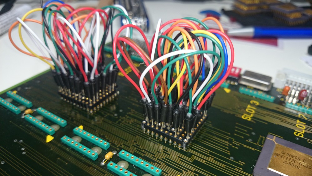
First I had to chew myself through the B012 schematic to understand the connection of each TRAM slot into the C004s. After that it was time for some intense cable plugging:
If you plan to do so, please be aware that the socket holes are too thin for a normal (0.63mm?) jumper cable. You might ruin your socket if you use force to plug them in!
I created a interpose socket by using single row pin header sockets which itself had thin enough pins to fit into the original B012 socket.
After some corrections, the buzzing-through of all 16 slots went fine and the schematics went to the PCB house (I have some PCBs left, ask for a quote if you need some).
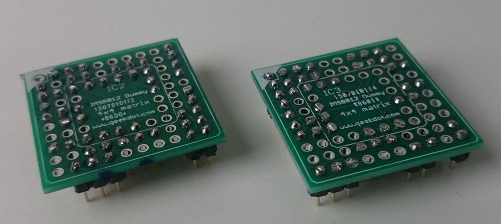
And this is how the C004 replacement PCBs look when completed:
Again, to solder in the pins, you’ll need really thin ones. Thinner than 0.5mm that is. Also, you don’t need to populate all 84 pins, I only use 51 per dummy (bridging some gaps).
Additionally, I strongly advise to isolate each dummy’s top with some kind of tape to avoid (electrical) contact to the TRAM placed above it. This is how they look seated on the B012 underneath slot 6 and 14 – the T212 under slot 7 not yet removed:
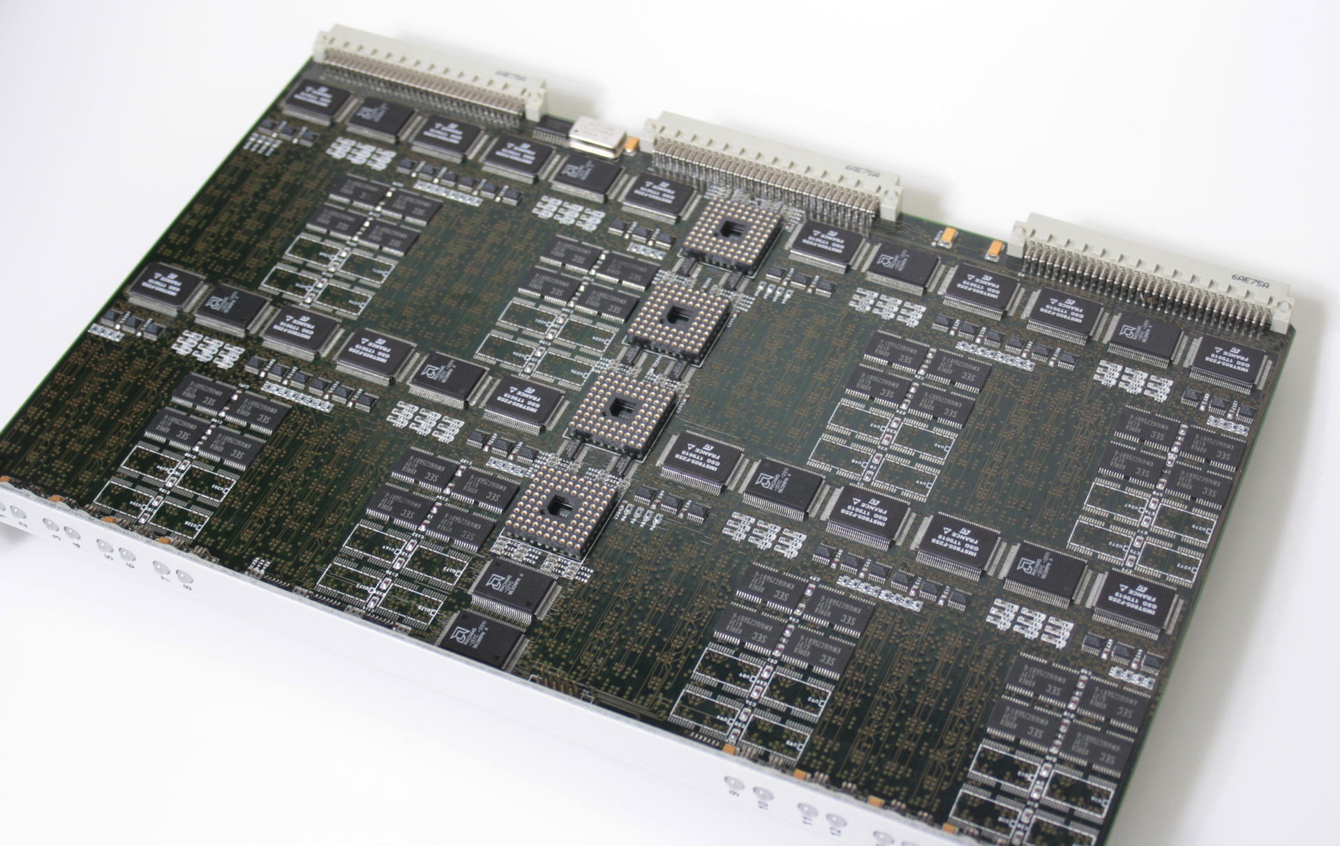
The Transtech TMB316 never really seemed to see the light of day and is probably one of the last Transputer developments of AG Electronics for Transtech. Internally it’s also been called the “MTPA-0001”, MTP translates into Multi Transputer Platform, most likely “A” for 2MB and version 0001.
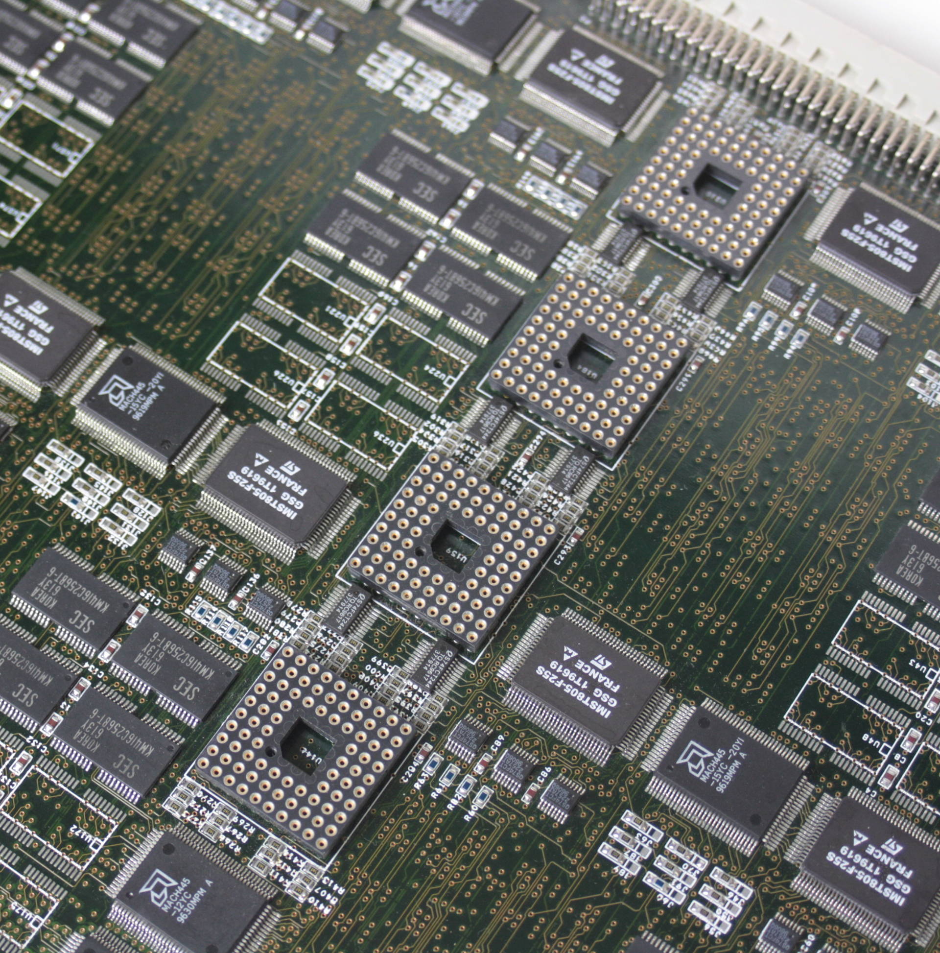
It’s a triple-height Eurocard board featuring 16 T805 at 25 or 30MHz, each with 2 or 4MB RAM. This is the card in full beauty:
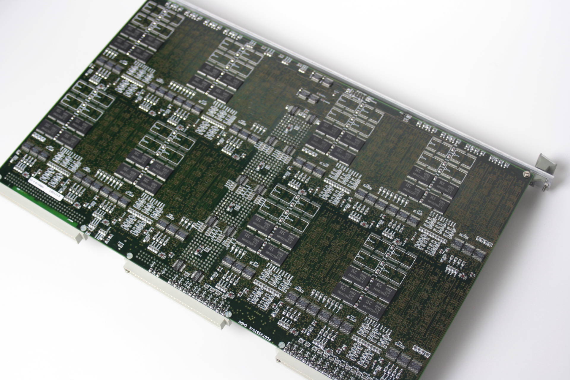
As you can see, it’s not totally cramped with parts and actually has quite uncongested areas. The reason for that is, that this model (Called TMB316-2-25) only uses 2MB of the possible 4MB RAM per Transputer and while all Transputers are placed on the top side of the PCB, every second Transputer has its RAM on the bottom side, right beneath the ‘free space’ visible on the top. This is the back side (flipped horizontally):
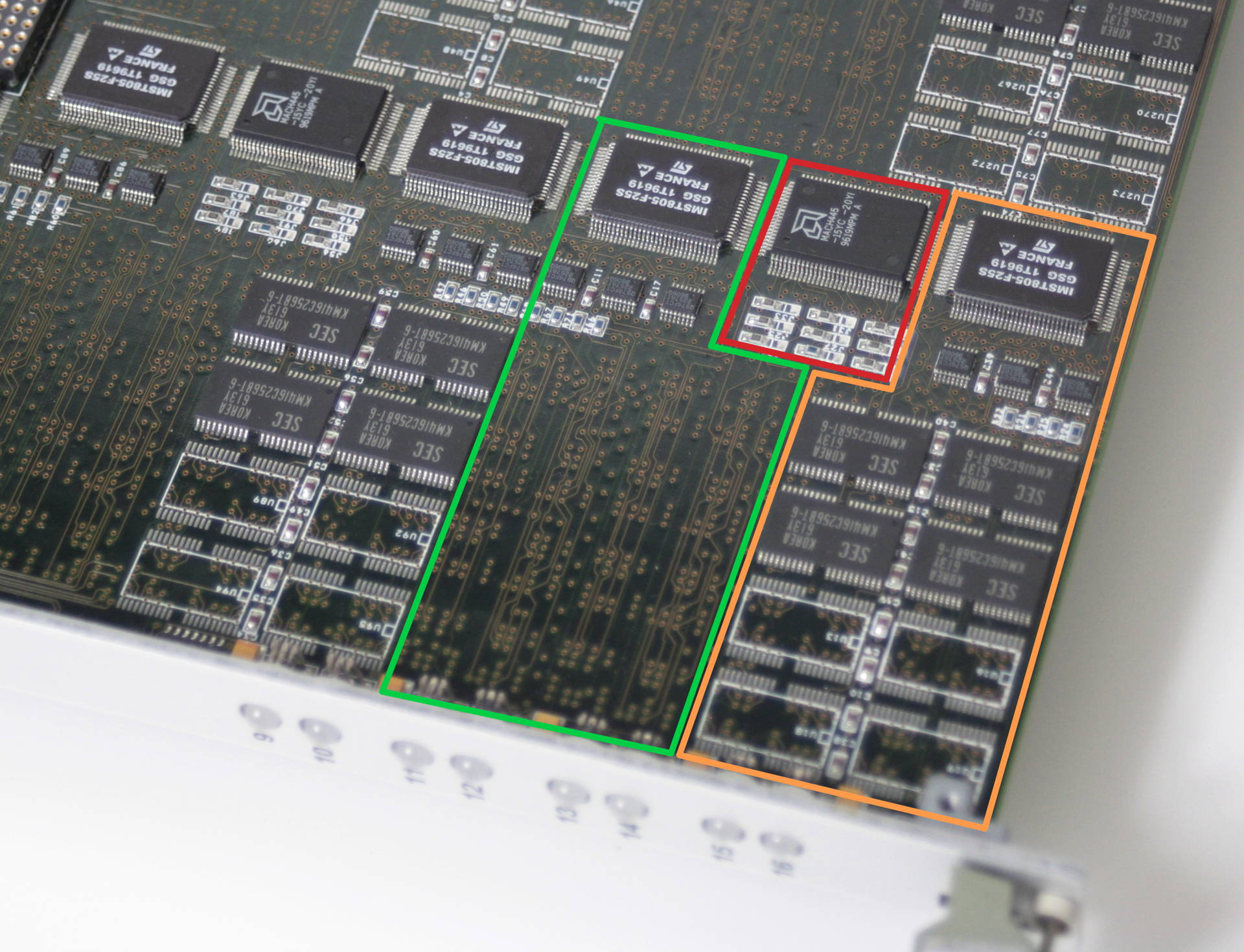
It becomes more obvious, when we zoom into a Transputer section of the board:
I coloured each Transputer (green and orange) with its RAM area. The red area shows the CPLD which is shared between the two Trasnputers and handles the DRAM control and such.
Also visible on the cards front panel are 8 of totally 16 LEDs which display each Transputers status.
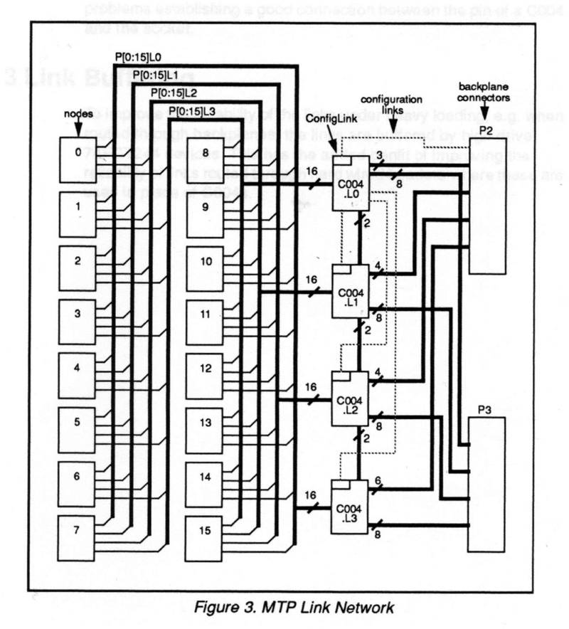
Obviously meant for a bigger systems, Transtech/AG Electronics planned the TMB316 for big deployments, i.e. more than one card. So each card uses four C004 link switches which connect the 16 T805 to each-other as well as to the outside world via the DIN connectors at the back of the card (totally non-standard pinout). This is fine if reconfiguration of the T-network is important but there’s no alternative but using dummy PCBs if all you need is speed. And being an avid GeekDot reader, you know my view on C004’s 😉
This is where the C004s were meant to live.
Just in case you really want to know, here’s how the Transputer nodes are connected to the 4 C004 and to the backplane connectors:
Ok, so you have your shiny (not so) new Transputer system installed/connected and you really like to know if it works and at least see some results… you’re in need of basic Transputer tools to get started.
Even it’s historically not the first application ever developed for Transputers it’s for sure one of the most used.
It started as ‘check‘ and at some point got renamed into ‘ispy‘ – whatever the name is, the technical term would be “network worm”. This means it’s a special piece of code which a) sniffs around in a transputer (what kind, number of links and their speed) and b) replicates itself over all links it previously found.
When done, it outputs a network map like this example:
ispy is used on geekdot.com extensively, so any time I write about Transputers you will see some sort of ispy output for sure. There are several versions of ispy included in this kit. This is because some versions behave more stable than other in certain circumstances. E.g. the most recent version 3.23 does not work very well with the C004 link-switches.
“The other part” of ispy is called mtest. mtest takes ispys output and runs an indepth memory test/report on all Transputers found.
iserver
iserver is part of what INMOS called “itools” – long before Apple discovered the “i” for themselves 😉 – there were many others, mainly development focused (e.g. idebug, icconf etc.).
It is more or less the successor to the godfather of all Transputer booting tools “afserver” (1988). Well, it has to be, being the on INMOS supplied with all their other tools and languages.
The possible options are quite self-explanatory and printed to stdout when omitting any option:
Basically if you see a *.btl, *.b4 or *.b8 file it’s most likely meant to be executed with iserver. Before running successfully iserver need some environment variables set to successfully to be used:
set IBOARDSIZE=#100000 set TRANSPUTER=#150
These two settings tell all itools how much RAM the Transputer has to work with and at which port address it can be found (0x150 is default anyway). The archive contains V1.42h from Nov. 1990 which is the most recent as far as I know.
Mandelbrot
The “CSA Mandelzoom Version” is one of my favorite benchmark tools. I like it so much, that I run it once a while just for fun.. and to extend my benchmark table which I’ve collected over the time using it.
It is nice because it features integer (T4xx) as well as floating point (T8xx) versions of the calculation ‘slave processes’ and scans the network itself. No external tool needed. It’s also possible to let the host (i.e. your PC) calculate the Mandelbrot fractal to get an idea, how much faster/slower your Transputer network is – the archive contains a little benchmark result text file which I accumulated over the years.
Also there are some handy switches available (‘-h’ for help):
-v : Use VGA graphics
-t : Run on host instead of Transputers
-a : Autozoom, loads a list of coordinates from man.dat and start calculating them without manual interaction.
-b : Use a different base address (instead 0x150)
-x : Verbose output of the Transputer initialization process (added by me)
After a while I got tired of manually time a calculation run and also ran into problems with large networks which simply became to fast to hand time. So I extended the code of Mandelzoom with a high precision timer (TCHRT, shareware, can’t remove the splashscreen, sorry) which prints out a timer summary when run with the “-a” parameter. I provided my default “MAN.DAT” file, which contains 2 coordinates to calculate (1st & 2nd run) and used for all my benchmarks.
These are the results of my DOS host system running in VirtualBox.
Caveat: It breaks if there’s a T2xx in the network (e.g. B008/B012) 🙁 And as always: Read the F-ing README.txt!
Since I started to heavily modifying the source, I wrote a post of its own about it as well as put everything on github, so you can join the fun 😉
Other Tools
iskip
iskip can be very handy, when ‘talking’ directly to (externally) connected links, e.g. another network which is connected to your root Transputer. Here’s a good example:
You like to put code directly onto “processor 1” which is connected to link 2 of your root Transputer:
So you call
iskip 2 /r /e
This sets up the system to direct the program to the target network over the top of the root transputer and starts the route-through process on the root transputer. Options ‘R’ and ‘E’ respectively reset the target network and direct the host file server to monitor the halt-on-errorflag. The program can then be loaded ‘through’ the root Transputer directly onto processor 1 using:
iserver /ss /se /sc test.btl
debug.exe
Yes, I do mean the comes-with-DOS debug.exe. Well, you can use any debugger you like as long it can read/write to port addresses.
Obviously this means [MS|PC|Open|Free]DOS only. You won’t get far with this on Linux, any Windows or OS/2. At least for initial debugging and testing I strongly recommend to use the “bloated interrupt manager” known as DOS.
First of all, you have to know the port addresses the C012 registers are mapped to . There’s a de-facto industry standard which INMOS introduced with the IMSB004. Its been adopted by 90% of all 3rd party products, even with certain ISDN cards using Transputes.
The base address normally is at 0x150 (which can be configured to other addresses in some cases). From this base adress the offset is always the same:
Base Adress
Register
Comment
+0x00
C012 input data
read
+0x01
C012 Output data
write
+0x02
C012 input status register
read = returns input status
write = set input interrupt on/off
+0x03
C012 Output status register
read = returns output status
write = set output interrupt on/off
+0x10
Reset/Error register
write: Reset Transputer & C012 and possibly subsystem (check manual)
read: Get Error status
+0x11
Analyse register
(un)set analyse
So here’s a clean Transputer setup ‘conversation’ using debug (comments are just for clarity, not supported in debug):
c:\>debug
-o 160 1 # Assert RESET-o 161 0 # Deassert ANALYSE-o 160 0 # Deassert RESET ... init B004/IMSC-o 152 0 # Clear Input Interrupt enable-o 153 0 # Clear Output Interrupt enable-i 152 # Read Input Status00 # Bit 0 = 0 -> no Data waiting
-i 153 # Read Output Status
01 # Bit 0 = 1 -> ready to send-i 160 # Read Error00 # Bit 0 = 0 -> ERROR not signaled
-o 151 1 # send POKE
-i 153 # Read Output Status
01 # Ready -> POKE Ack (00 = BAD no Transputer)
After that you’re fine to send and receive bytes through 0x151/0x150. Doing so, you’re completely free which programming language to use. Here are some examples in AppleSoft Basic or even Python.
home of real men's hardware
We use cookies on our website to give you the most relevant experience by remembering your preferences and repeat visits. By clicking “Accept”, you consent to the use of ALL the cookies.
This website uses cookies to improve your experience while you navigate through the website. Out of these, the cookies that are categorized as necessary are stored on your browser as they are essential for the working of basic functionalities of the website. We also use third-party cookies that help us analyze and understand how you use this website. These cookies will be stored in your browser only with your consent. You also have the option to opt-out of these cookies. But opting out of some of these cookies may affect your browsing experience.
Necessary cookies are absolutely essential for the website to function properly. This category only includes cookies that ensures basic functionalities and security features of the website. These cookies do not store any personal information.
Any cookies that may not be particularly necessary for the website to function and is used specifically to collect user personal data via analytics, ads, other embedded contents are termed as non-necessary cookies. It is mandatory to procure user consent prior to running these cookies on your website.