Having the “Gerlach card” running, I was looking for ways to create something Transputers were made for: A farm, grid, network, cluster – call it what you like.
By a lucky incedent I was able to make contact to some people at DESY, which is one of the world’s leading accelerator centres. DESY develops, builds and operates large accelerator facilities, which are used to investigate the structure of matter. It’s comparable to the CERN accelerator in Switzerland.
I’ve learned that they were on schedule to switch-off a part of their accelerator, namely ZEUS (German), as all the planned research-protocols were finished… and I’ve learned that they use(d) several transputers for data aquisition and real-time analytics!
So after 2 years of shmoozing and sending ASCII-art flowers in mails, I was allowed to give their transputers a new home (else they would have been destroyed – oh my!).
I was surprised to see, that there was not the amount of transputers used as I would have expected (hundreds?). So no wonder they were able to replace the transputers by one single Linux box for the last year of the project, running the transputers as hot-standby backup.
But I also got all their spare-parts and everything else… a good start.
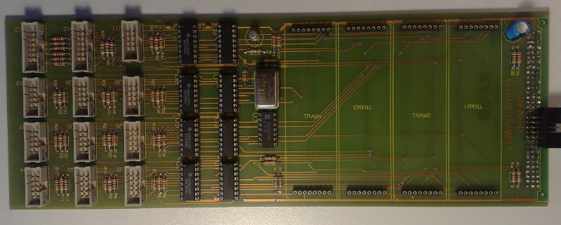
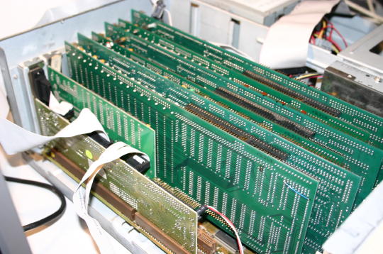
The original system consisted of 12 transputers, each on a TRAM, 4 of those sitting on a custom made TRAM-board called “TRAMWAY” which looks like this:
It’s not really worth calling it a board – It’s mainly a TRAM carrier with RS422 drivers for each link. The links for the TRAMs are hardwired, so TRAM1 has one “down link” (i.e. from the host or another card) connected to link0. Link1, 2 & 3 are connected to TRAM1, 2 & 3 respectively.
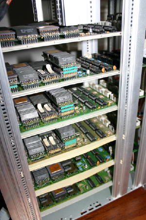
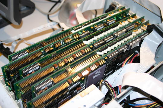
6 of those TRAMWAYs are currently sharing a case making it The Tower Of Power:
As you can see I stacked some TRAMs (Size-1 TRAM on a size-2 TRAM) to squeeze in the maximum number of TRAM… power to the tower, man!
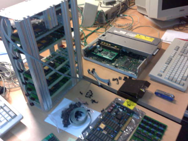
Here’s another one showing the ToP with its host, an Intel LP486:
Kerberos is the machine I’ve specifically built for hosting all 3 DSM860 cards I own.
The name was chosen because the hell-hound Kerberos (Latin ‘Cerberus’, Greek ‘Κέρβερος’) is mostly depicted with three heads and the Greek myths offer innumerable possibilities for a nice g[r]eek name space 😉
The quest for the right motherboard was not easy. It should be small, still featuring as many EISA slots as possible. In the end it became a Gigabyte GA-486SA having some quite unique features for its time:
8 EISA slots
2 of them also having Vesa-Local-Bus connectors
A Weitek 4167 Socket
8 SIMM slots
Because it was clear I will use-up 6 slots just for the 3 DSM860 cards (being sandwiched boards) I wanted to fill the remaining 2 slots as clever as possible.
After another year (!) of searching I was able to get my greedy little hands onto a Western Digital ‘Ports’o’Call‘ Vesa-Local card. This is a rare do-it-all card saving lots of slots, specifically:
WD90c33 VGA (1-2MB) connected to the VL-Bus (fast!)
Appian Local Bus IDE controller (also quite fast)
Floppy controller
2S/1P peripheral controller
In a sentence: Everything a basic system needs to work! The remaining slot was planned for a NIC making the system complete.
Because I was expecting quite some heat coming from the three i860 I’ve opted for a desktop case so that the heat can easily dissipate through the open casing – also I was prepared for lots of plugging and unplugging of cards, jumpers etc. which is much easier with a desktop case.
Golden Rule #1 of hardware fiddling: One step after the other!
So before filling the system up to its rim, I started with just one DSM860. It quickly became clear that there was no way in using the ports’o’call’s WD90c31 as the server running on the DSMs does only support certain VGA cards (if you like to have graphic output), namely some very obsolete, non-standard Genoa cards…and in its latest version: Good old ET4000!
So the nice ports’o’call had to make place for a standard multi-IO controller and the 2nd slot was used for an ET4000. That setup worked quite nicely!
After the last DSM860/32 board was fixed, I was ready to “stuff that turkey”.
One card after the other went into the slots – that’s what I call a crowded house:
As the animation above is not the highest quality (file size!), here are some more shots…
All seats taken, sorry:
The money-shot 😉 Indeed… in 1991 you would have payed 48.000 German Marks (~US$ 24k) for the DSM860’s alone… plus a 486DX/2 system with a whopping 32MB of RAM (~9500 Marks = ~US$ 4750). So that’s a total of $US 28.750 or the average income/year (1991) in the US.
Finally some of Kerberos facts:
3 x i860/40MHz each 8MB RAM (= 180-240 ‘marketing-MFLOPS’ / 360 ‘marketing-MIPS’)
Handcoded code using LINDA SMP techniques can realistically reach ~80 MFLOPS on this system, that’s about the speed of a Cray-1 or … a Pentium Pro 200 :-/
1 x 486/DX2-66, 32 MB RAM (~3.5 MFLOPS)
Complete system (w/o display) draws 140W when running full steam ahead. Which is about the same a recent (’09) Intel Core2/Core i7 or AMD Phenom needs @ 3.2GHz – just the CPU though!
Meet Sparky 2, my main Solaris box. Yeah, Sparky2 isn’t exactly a roman or greek mythical figure, even the ‘sun theme’ would give you hundreds of possible god, godess and daemon names but there’s a reason. Sparky2s main reason d’etre is Helios core development. As far as my research in the sources went, Perihelions main dev-box was called Sparky – so to honor their work I continued to use this name.
Hardware
Sparky2 is actually the 2nd incarnation of my Solaris dev-box. “Sparky-1.5” was/is a lovely SparcStation 20, dual SuperSparc-60 CPU, 384MB RAM and even a on-board CG14-Framebuffer.
But that beast is just loud. Loud fans and a loud SCA-SCSI drive. As with most of my vintage computers, I was thinking and planning to replace everything to make it nearly noiseless but while the power-supply fan was doable, the hard-drive replacement would result in unjustifiable costs… and still it wouldn’t been any faster then.
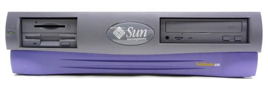
So here it is, the ultimate “Solaris-Box-which-can-run-even-in-your-bedroom™”: A Blade 150.
Yes, you’re right, pretty recent stuff (2000-2006) for Axels ususal crap equipment, and in a Sun hardware evangelists view, it’s not even worth being called “a SUN”, but I needed it to run silent, and because the Blade 100/150 series is mainly build from standard PC parts, it’s perfect for noisless tuning.
It comes in a small ATX-desktop case, uses IDE drives, a standard ATX power-supply, standard PC133 ECC DIMMs (cheap these days!) and the 650MHz UltraSparc IIi CPU is fast enough to compile any vintage project in matters of minutes and not hours.
So out went the power-supply fan as well as the case-fan in the front and both were replaced by my noise-killer-of-choice: BeQuiet! fans.
The supplied Seagate IDE drive is already very silent, so I didn’t replaced that by some IDEtoSDCARD adapter or even a SSD (no, it wouldn’t be faster, the interface is ATA66).
As for the CPU-fan I was told that some (more silent) NVIDIA fans perfectly fit – need to try that later found a better solution, see post below.
Software
Depending what you’re planning to do with it, a blade supports IIRC Solaris from version 7 up to 10. In my humble opinion Solaris 8 is the best OS to fiddle around with vintage sources: “Modern” enough and still featuring SunOS 4.1.x compatibility through the ‘SunOS Binary Compatibility Package” (called SUNWbcp).
While not necessarily needed for vintage coding, I still think it’s a must-have: pkgutil from the OpenCSW project – especially since Sunfreeware is unixpackages.com now, which isn’t free anymore.
Contrary to this, pkgutil is the ultimate & free package-manager and just works as you might got used on other platforms (yum, ipkg and such). It’s much of a relief when you finally got basics like bash, less and another-editor-than-vi etc. Here’s how to get started.
Most important of all, you’ll obviously will need gcc. I had good results with GCC 2.95 which is not available on OpenCSW, but if you know how to Google, you’ll find it for sure 😉
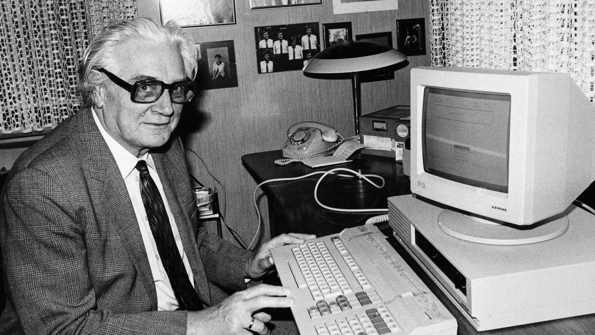
The Siemens PC-X is an oddball from the very early days of the PC/XT world. And as you might have seen yourself browsing this page, I have a soft spot for the oddballs… ok, now for the facts:
It is based on the original “PC-D” design. Actually besides the ROM, the (optional) MMU, a slightly different graphics card and a hard drive as standard they’re the same… BUT the “X” came with SINIX, Siemens’ XENIX based flavor of UNIX. That’s somewhat impressive when you check out the rather limited specs:
8MHz i80186 CPU
1MB RAM
10-20MB hard drive (depending on drive used)
640x350x1 bit Black on white display – that was very high-rez back then
Yes, the PC-X/D were one of the few machines using the 80186 instead of the “industry standard” 8088/8086.
That move seemed to be advanced but it was a step backwards actually, because all those machines were more or less incompatible to the available, ever-growing MS-DOS software library.
For the “X” model, it was even worse. Running SINIX you more or less totally depended on Siemens for getting Software. There was their own office suite and you could buy MS Word/Multiplan/Chart and dBase II from them. Well, pretty ok to run a multitasking( !) office system in 1984. Here’s a video showing a Siemens PC-X booting into SINIX:
Because nearly everything was non-standard in this beast (graphics, expansion bus etc), its career didn’t take long. I love the keyboard, though. It looks very 80’s and is another example of German over-engineering: You can run over it with your car, it’ll still works – like an IBM Type M.
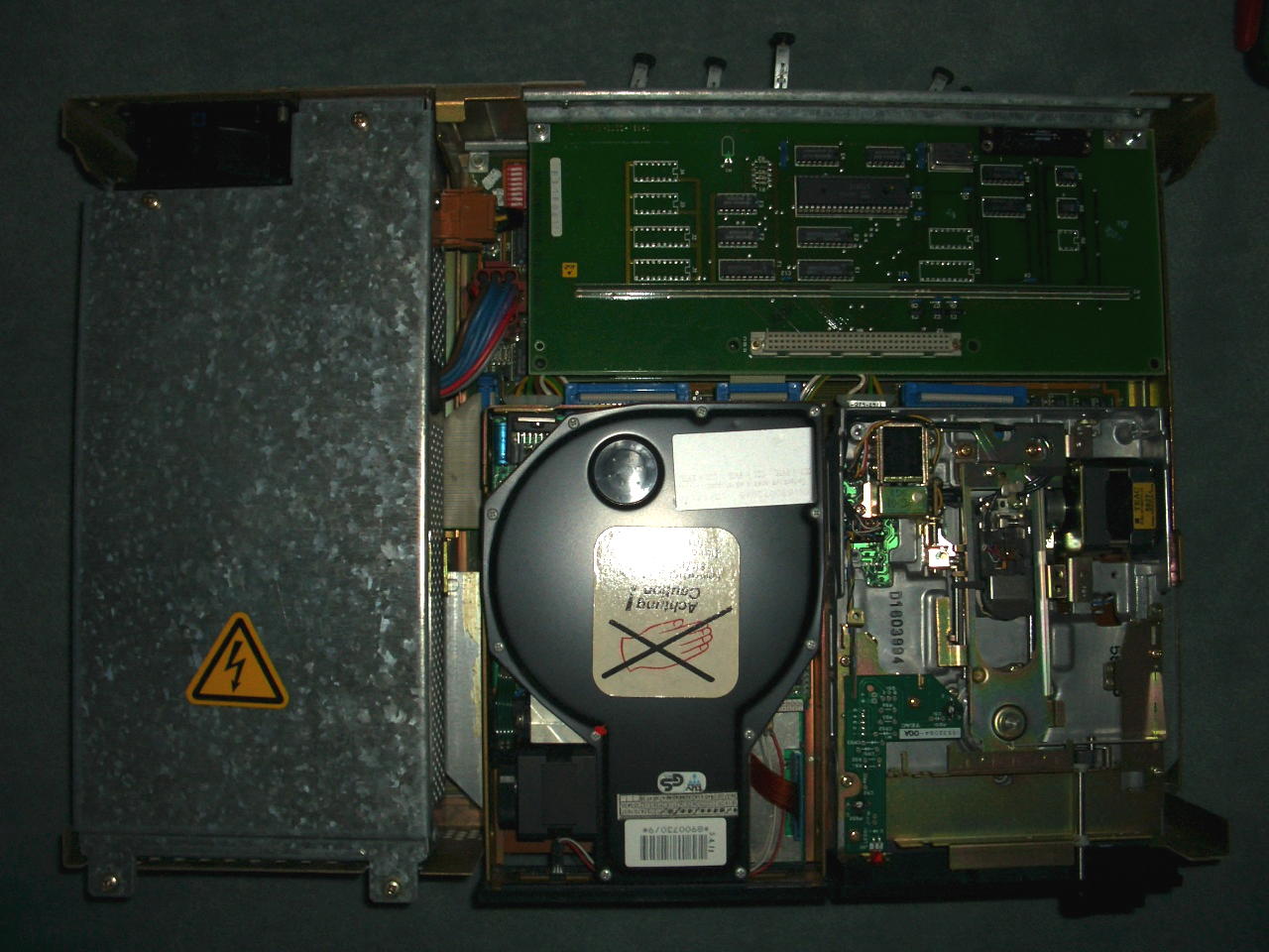
This is what you see as soon you opened the 0.8mm thick steel case – left 3rd the huge power-supply, front drive case, back the mezzanine bus:
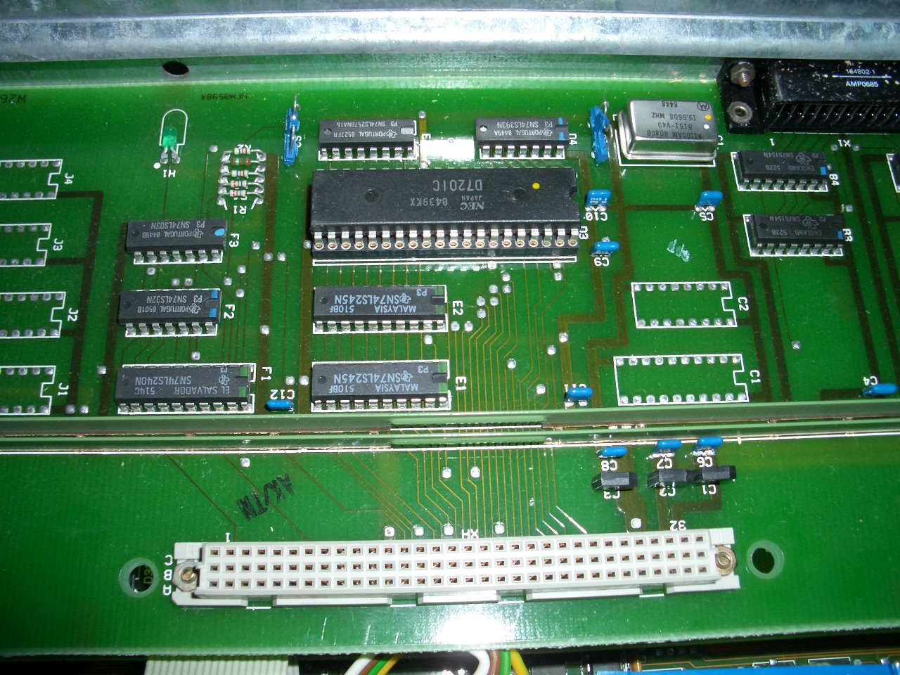
Remove the drive-cage (Left: BASF 6188 10MB MFM hard drive and right: TEAC FD-55FV floppy) and you’ll see the GPIB/RS232 expansion card – very simple NEC D7210 design – the external connector is marked “DFÜ” (German acronym for “Datenfernübertragung”, i.e. Modem and stuff) :
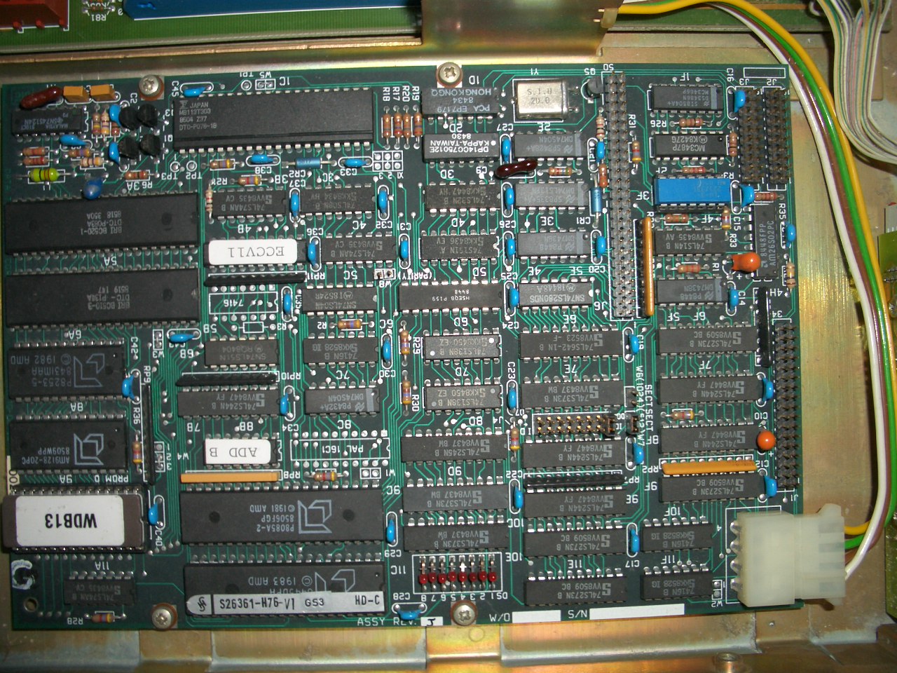
Next in the “stack” is the graphics card which also controls the keyboard. It seems to be different from the one used in the PC-D version. Left side a 8031 and a SCB2673 (Video attributes controller), 2 EPROMs (D39/40) and a 2k SRAM.
Right side, a SCN2672 (Programmable Video Timing Controller) with its own 8K EPROM (D12) and 4k of SRAM:
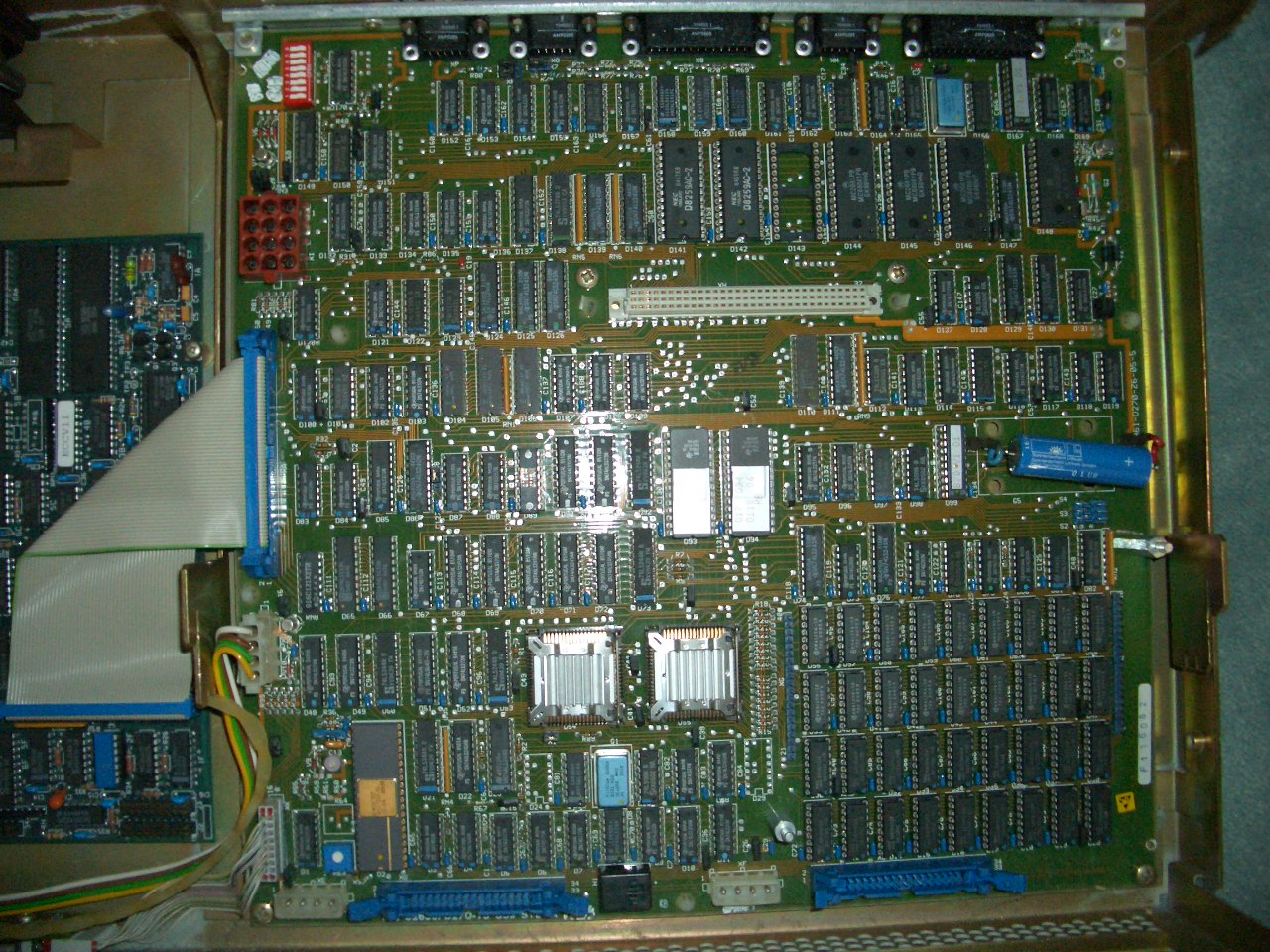
Having removed that expansion board you have the full view of the main board – Bottom right the RAM, left the CPU, a WD2791 Floppy controller and of course the 80186 CPU and a C8207-8 memory controller (which I falsely identified as MMU) next to it:
If you also remove the power supply, you will find another odd thing (also a bit visible at the left edge of the above picture): A SCSI-to-MFM converter board, the “DTC 520B“. So SIEMENS decided it’s better to fit an MFM hard disk and this converter than using the on-board SCSI bus an provide an (expensive) SCSI drive. Mhhh…
The reason to finally write this post is that I was asked for an image of SINIX and of the PC-X’s ROM to get the whole thing emulated in MESS.
So here are the ROM images of what I have. Maybe I’ll be able to add some more floppy images… stay tuned.
Other versions
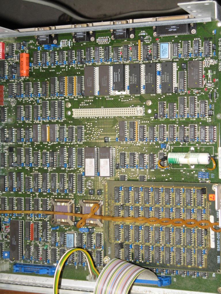
While browsing the web, I came about another version of the mainboard and graphics-card. According to their model numbers and their design, they seem to be predecessors of my boards.
Here’s the mainboard. While mine has model W26361-D270-Z6-05-36, this one is marked -D270-Z6-02-05.
Many ICs are featuring a ceramic case. The RAM seems to be put on a separate PCB
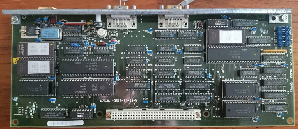
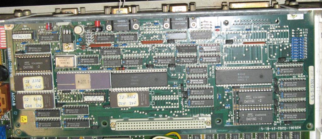
The graphics-card has more differences (mine is W26361-D310-Z4-03-5, this one is -D282-Z4-10-5. The ICs are placed differently, its design looks more cluttered and some ICs aren’t populated on the board at all.
Tips
If you got your SINIX running -maybe a previously installed version- and you cannot get root access here’s a hack to get root access (assuming you can login as guest w/o password (commonly named ‘gast’). It bases on a mistakenly set permission:
/usr/lib is writable for everybody
$ ls -ld /usr/lib drwxrwxrwx root /usr/lib
in there is a crontab file. Copy that to /tmp, delete the original and copy your version back to /usr/lib to make it yours:
Now you can edit ‘your crontab’ with an editor (ced) and add one line like this:
* * * * * /bin/chown gast /etc/passwd
So after one minute /etc/passwd is yours, too.
Now you can remove roots (or admins) password by changing
root:cHuykydasds: (or something like that)
to
root::
Voilá, this SINIX is yours 😉
Another thing you might need is to move data in/out. The only initial way to do this is a tool called ‘trados‘. This can read/write 360KB (only!) DOS floppies. At least a start…
Next steps
Finally, when revisiting this machine after quite some years in my basement, there are some tempting things to check out:
Can I replace the DTC 520B and use a SCSI drive directly?
As the SRAMs on the graphics board are sitting in bigger sockets – what will happen if I use bigger SRAMs? This might be answered when the emulation is working and we can fiddle with the video firmware to use more SRAM.
Meet The Cube – this is the Transputer Power-House successor to the Tower of Power, which was a bit of a hacked frame-case and based on somewhat non-standard TRAM carriers with a max. capacity of just 24 size-1 TRAMs…
The Cube hardware
This time I went for something slightly bigger 😎 …A clear bow towards the Parsytec GigaCube within a GigaCluster. The Cube uses genuine INMOS B012 double-hight Euro-card carriers, giving home to 16 size-1 TRAMs – Parsytec would call this a cluster and so will I.
Currently The Cube uses 4 clusters, making a perfect cube of 4x4x4 Transputers… 64 in total. Wooo-hooo, this seems to be the biggest Transputer network running on this planet (to my knowledge)
If not, there still room left for more 😯
Just to give you a quick preview, this is what ispy responds when ran against the Cube:
32 x T800@20MHz/1MB (mainly TRAMs from MSC and ARADEX)
-> 96MB of total RAM
-> 70-130 MFLOPS (single precision)
~800MIPS combined integer power
~60Amps @5V needed (That’s 300W 😯 )
So we’re talking about 70-130 MFLOPS here – depending which documentation you trust and what language (OCCAM vs. Fortran) and/or OS you’re using. That was quite a powerhouse back in 1990 (Cray XM-P class!)… and dwarfed by a simple Pentium III some years later 😉
Just for to give you an comparison with recent hardware (Linpack MFlops):
Raspberry Pi Model B+ (700 MHz)
~40 DP Mflops
Raspberry Pi 2 Model B (1000 MHz – one core)
~134 DP Mflops
Raspberry Pi 3 Model B (1200 MHz – one core)
~176 DP Mflops
Short break for contemplation about getting old…
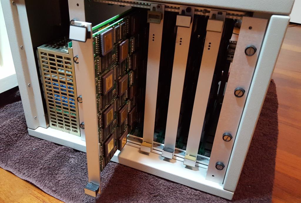
Ok, let’s go on… you want to see it. Here it is – the front, one card/cluster pulled, 3 still in. On the left the mighty ol’ 60A power supply:
Well, this is the evaluation version in a standard case, i.e. this is meant for testing and improving. I’m planning for a somehow cooler and more stylish case for the final version (read: Blinkenlights etc.).
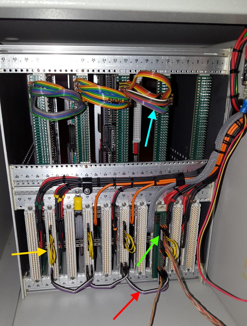
And here’s the IMHO more interesting view… the backside. It shows the typical INMOS cabling.
As usual, I color coded some of the cables.
The greenarrow points to the uplink to the host system to which The Cube is connected to. Red are the daisy-chained Analyse/Reset/Error (ARE) signals. The yellow so-called jumper-cables connect some of the IMSB004 links back into the boards network. And in the upper row (blue) four ‘edge-links’ of each board are connected to its neighbor.
This setup connects four 4×4 matrices (using my C004 dummies as discussed here) into a big 4×16 matrix. Finally I will ‘wrap’ that matrix into a torus. Yeah, there might be more clever topologies, but for now I’m fine with this.
Building up power
For completeness, here’s a quick look at how things came together.
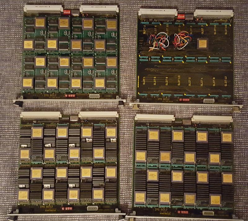
The 4 carriers/clusters with lots of size-1 TRAMs… upper right one is the C004-dummy test board (now also fully populated). Upper left is pure AM-B404 love <3
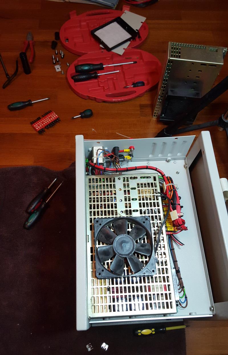
Fixing/replacing the broken power-supply (in the back), including the somewhat difficult search for a working cooling solution:
The Cube software
Well there isn’t any specific software needed to run The Cube, but it definitely cries out loud for some heavily multi-threaded stuff.
So the first thing has definitely to be a Mandelbrot zoom. As usual, I used my very own version with a high-precision timer, available in my Transputer Toolkit.
Here’s the quick run in real-time – you can still figure out visually each Transputer delivering its result:
So this is running fine – using internal RAM only. On the other hand, it seems that the current power supply has some issues with, well, the electric current.
When booting Helios onto all 64/65 Transputers which uses all of the external RAM, very soon some of them do crash or go into a constant reboot-loop.
By just reducing the network definition (i.e. not pulling any Transputers) to 48, Helios boots and runs rock-solid.
Because measuring the voltage during a 64-T boot shows a solid 5.08V on all TRAM-slots it most likely means the power supply either can’t deliver the needed amount of Amps (~60) or produces noise etc. 😥
So this is the next construction site I have to tackle.
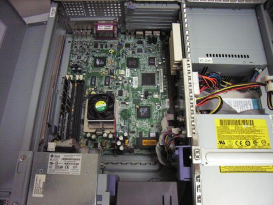
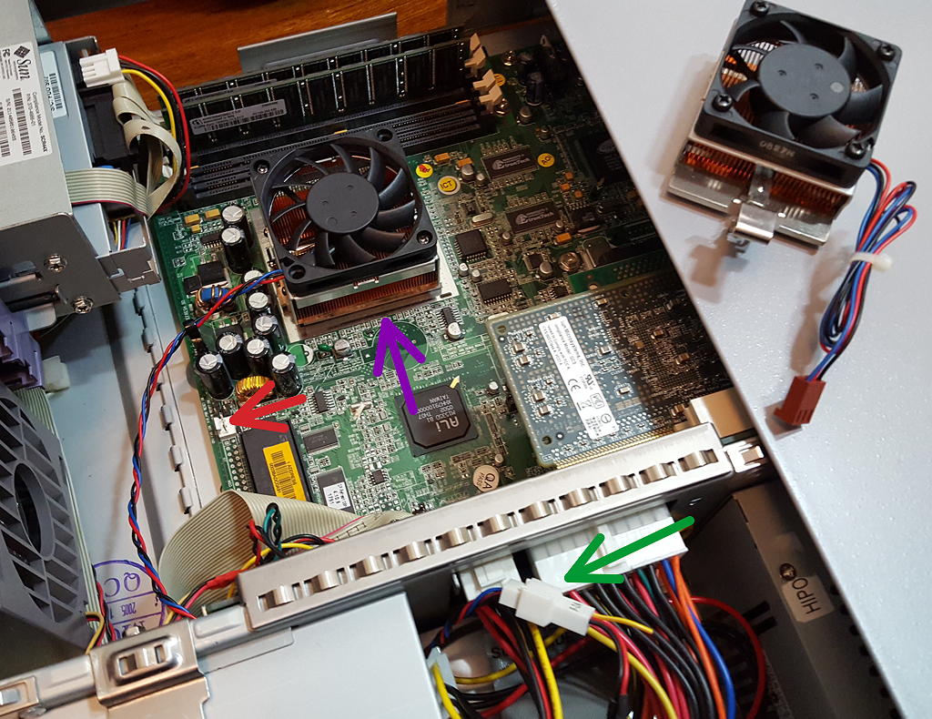
Working a lot with my Blade 150 called “Sparky2” recently, the CPU fan turned out to be too loud, still. So I dug deeper into the matter and it turned out easier than I thought…
SUN -for whatever reason- decided to put a comparably small 40x40mm fan on top of the non-standard heatsink and additionally placed some aluminum spacer around it.
Removing everything revealed a totally standard PGA 370 socket! That’s Pentium III, if you remember… So a quick check in my old-junk-stash resulted in 3 nice heatsinks. I took the full-copper one and mounted a 60x60mm fan on top.
Put everything into place – done (BTW: SUN didn’t use any thermal grease, so did I)… but the bigger fan was still too noisy at 12 volts 🙄
After checking the fan also starts at 5 volts, the decision was clear: Bigger, massive copper heatsink plus bigger fan should be sufficient at lower revs.
There’s no direct 5V source on the Blade 150 motherboard. So I chose the vacant connector for the optional 2nd hard-drive (the closer floppy connector would do, too – but I had no spare cable to salvage).
Simply connecting the fan there wasn’t enough. OpenBoot actually checks for the fan tachometer signal and refrains from booting the system without one connected.
I was already evaluating how to build a signal dummy (a simple 555 timer circuit) when I decided to check if a simple forking out of the signal is enough. So I used a 2-wire cable and put ground and the tachometer signal to the on-board fan connector… and voilá that made the OpenBoot happy. Finally silence!
Here’s a piccy.
Purplearrow: The new & bigger heatsink (the old on lies on to of the case, so it looks bigger than it actually is)
Red arrow: The original fan connector (it still misses the tachometer signal bypass in this photo)
Green arrow: This is where the new fan is connected.
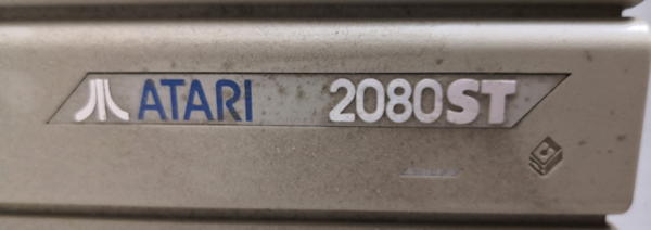
I bought this Atari 2080STF in 2003 and stored it as-is in my collection. The ST being my first 16bit machine I thought it could be a good point in time to un-dust and resurrect it 16 years later.
Atari 2080STF… 2080?? Yes, that’s true. There are different stories out there about their prototype/fake status.
As far as I see, there are two 2080STF versions out there:
The “Yugoslavian Version”
My Prototype
The Yugoslavian 2080STF is a pretty simple re-batching of a 1040ST which was upped to 2MB RAM and sold by a company called Mladinska Knjiga.
My 2080STF is different. In contrast to the Yugoslavian it features a proper, 3d embossed label, not some flat DIY thing.
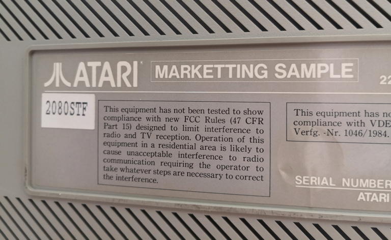
Instead of some serial# printing looking like made with a children-stamping kit it says this:
MarkeTTing Sample… should it have been an omen?
Marketting? Well… somebody’s been in a hurry or not native to English. Anyhow, the label shows the same quality as those used with Ataris produced in greater numbers. That said, there’s no serial number and the model ist just a paper-sticker.
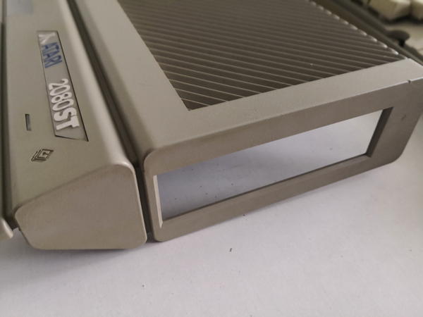
Next unique thing is the floppy cut-out on the right side. It’s the same square one like on a Falcon, but the plastics are in the proper ST grey. Mhhhh….
Looks Falcon’ish, but it isn’t…
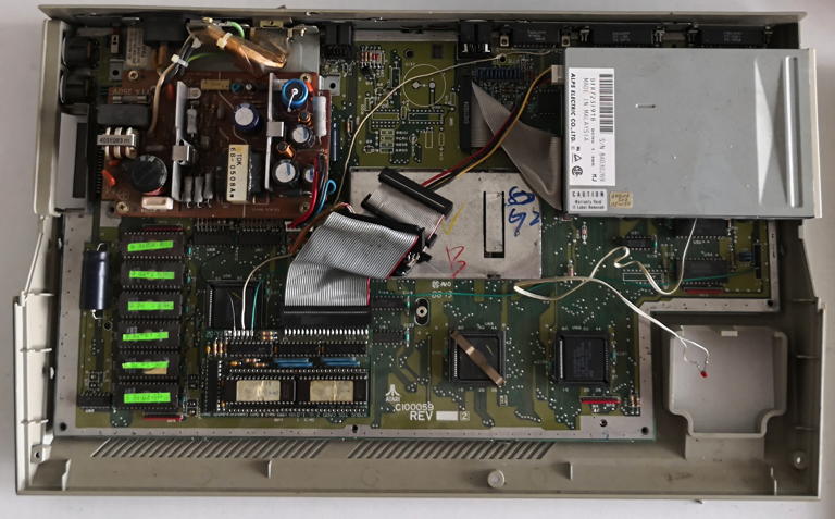
Finally the mainboard: Yes, it’s very 1040STFM without the M(odulator) part. But then it features a yet undocumented issue number of C100059, production week 8813. And mind the installed Blitter at the lower right.
Lots of ugly mods to be removed ASAP! But I’ll keep that IDE controller sitting on top of the 68k.
So what do we got here? Not having any matching-numbers system like in the vintage car world, we can only guess…
It might be a real “Marketing Sample” made for a planned pimp-up of the 1040 family. On the other hand it also can be a nicely composed Frankenstein system made of parts e.g. being sold at Ataris sell-out in 1995.
Given the sum of the unique parts being used, I opt for the “real marketing sample”, probably being put together using available parts and meant for checking out, if there’s a demand/market for such model(s)… and history taught us that there wasn’t.
Anyhow, I pulled out the crap which had been “installed” over the previous years…
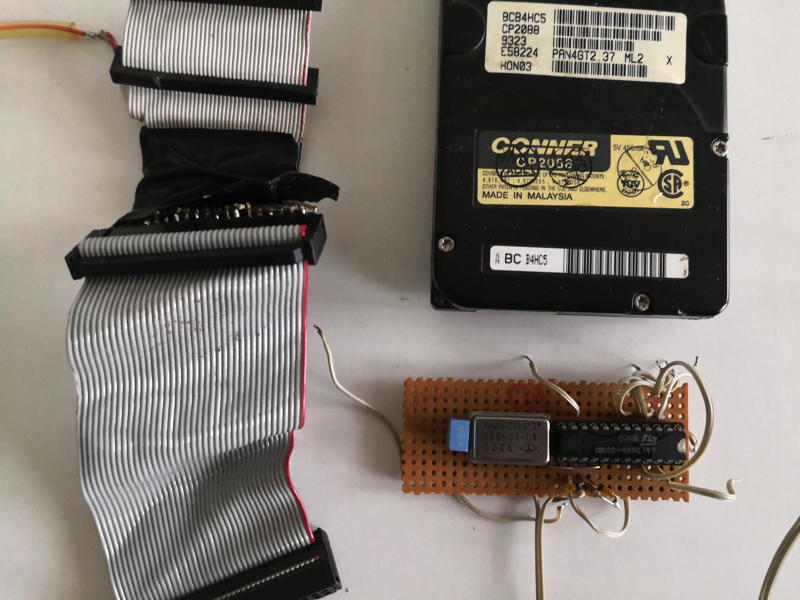
Boy, look at that IDE “cable adaptor”… a soldering nightmare. And who needs more than 19200 baud anyhow?
So the noisy 2.5″ 80MB harddrive got replaced by a CF-Card which nicely fits where the modulator would be, if this would be a STFM.
Additionally I 3D-printed a mounting thing for it which you can download here.
Finally, the build-in Hard & Software TOS-Card II 2.06 (that’s a long product name!) got fixed so it actually can switch between the on-board TOS and the 2.06 sitting on the card.
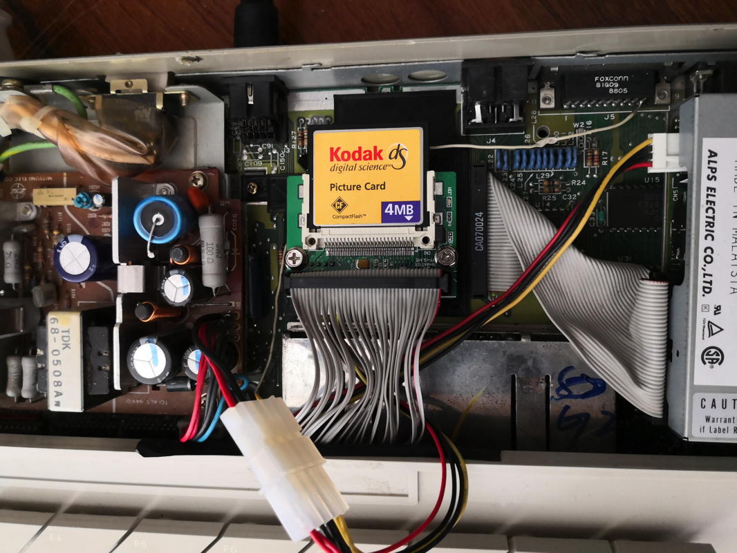
When everything’s done, it looks nice and tidy down there:
Yeah, that’s a 4MB card… just for testing. I took a “spliced” IDE cable I made ages ago – does a good job to squeeze underneath the keyboard.
So I think I’m all set for some pure 8MHz 68000 fun… oh boy, did I love those days.
Restauration
In 2026 (23 years after getting it!) I decided to give this rare ATARI more love… which it really deserves – shame on me!
So I stripped it to clean things and (again) freed it from all unnecessary things.
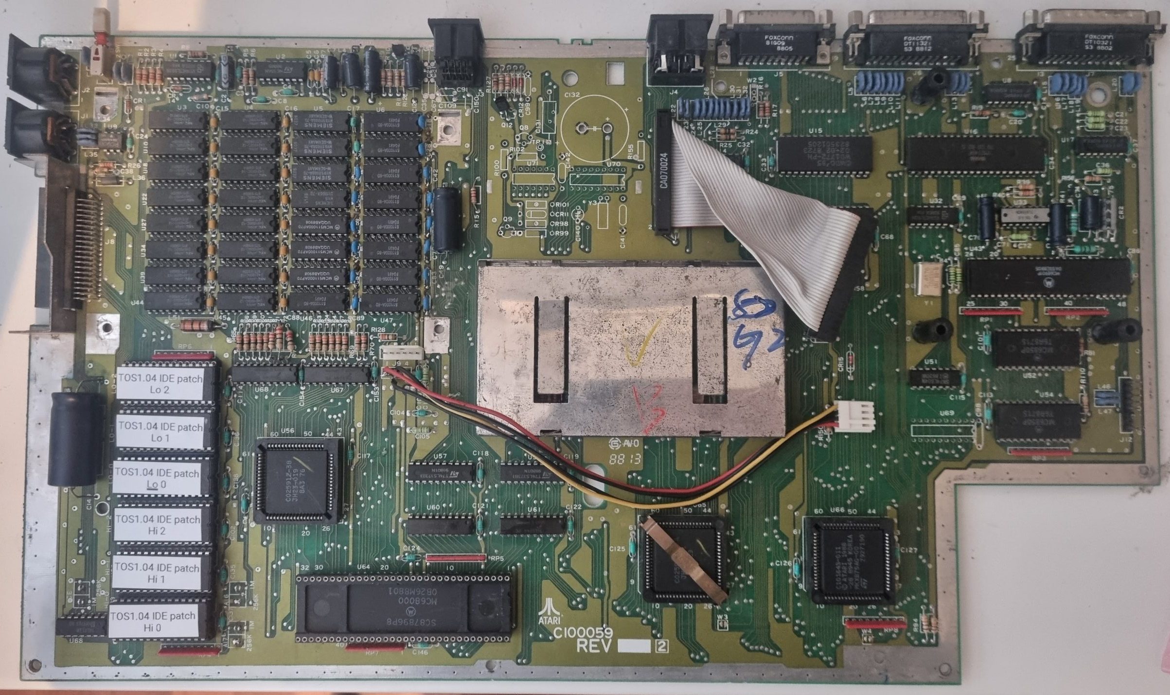
Here’s the bare board (Rev. C100059). I removed the TOS2.06 & IDE interface and the MAG!X ROMs, which I replaced by “contemporary” TOS 1.04 ROMs.
Like some of you mentioned, this prototype board has something very special, no all-in-one ATARI ever had:
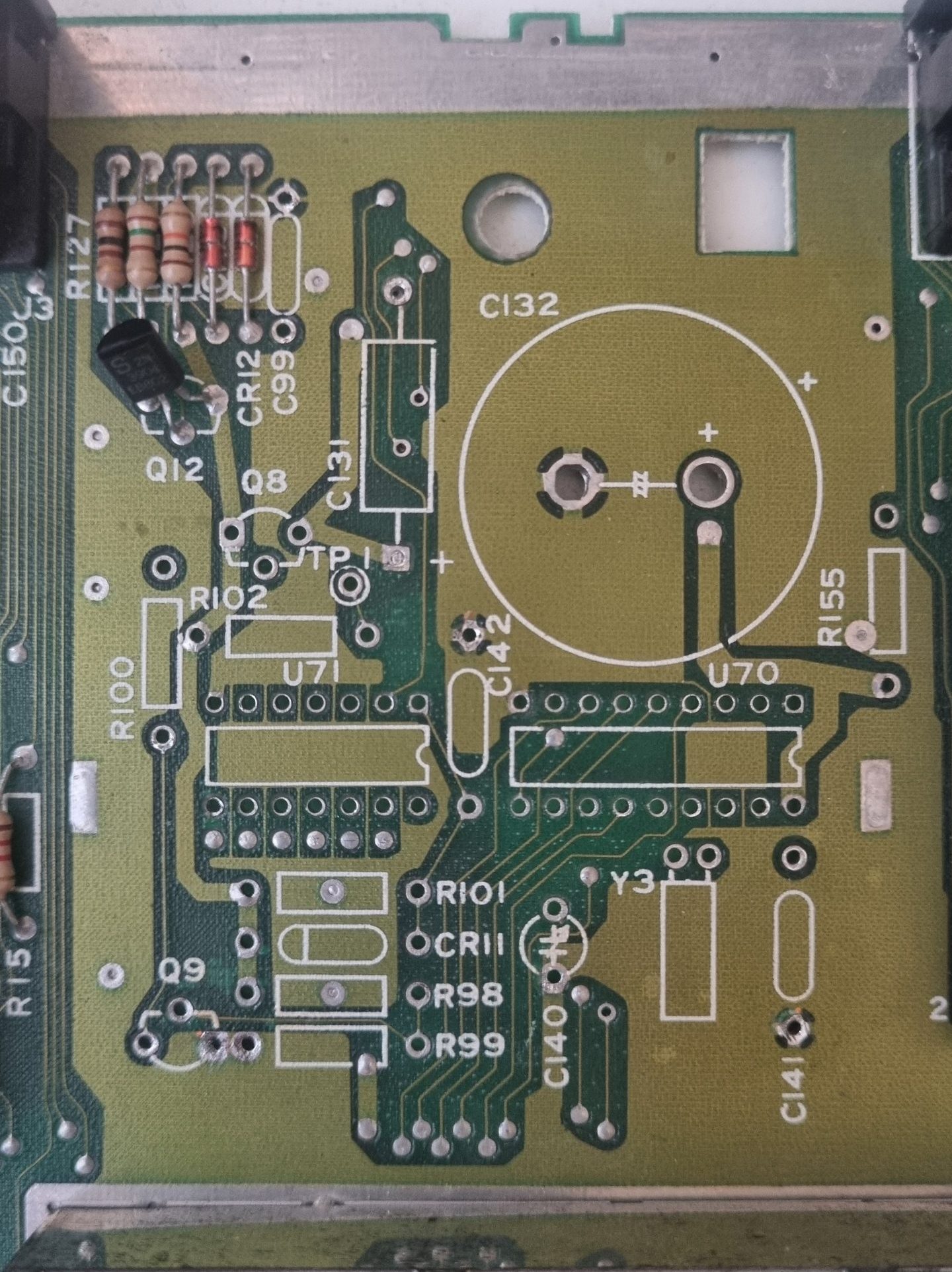
In the top-middle section of the board, where you’ll normally find the TV-modulator in an 1040STFM is an unpopulated space with a very suspicious marking:
[All solder-holes already cleared from solder by me]The coin-cell battery gives a clear hint: This is the real-time clock you’ll normally find in the Mega-ST series.
So even it’s a rare model, I thought: “Would it work? Was it left empty intentionally or they just hadn’t the time left populating it?”
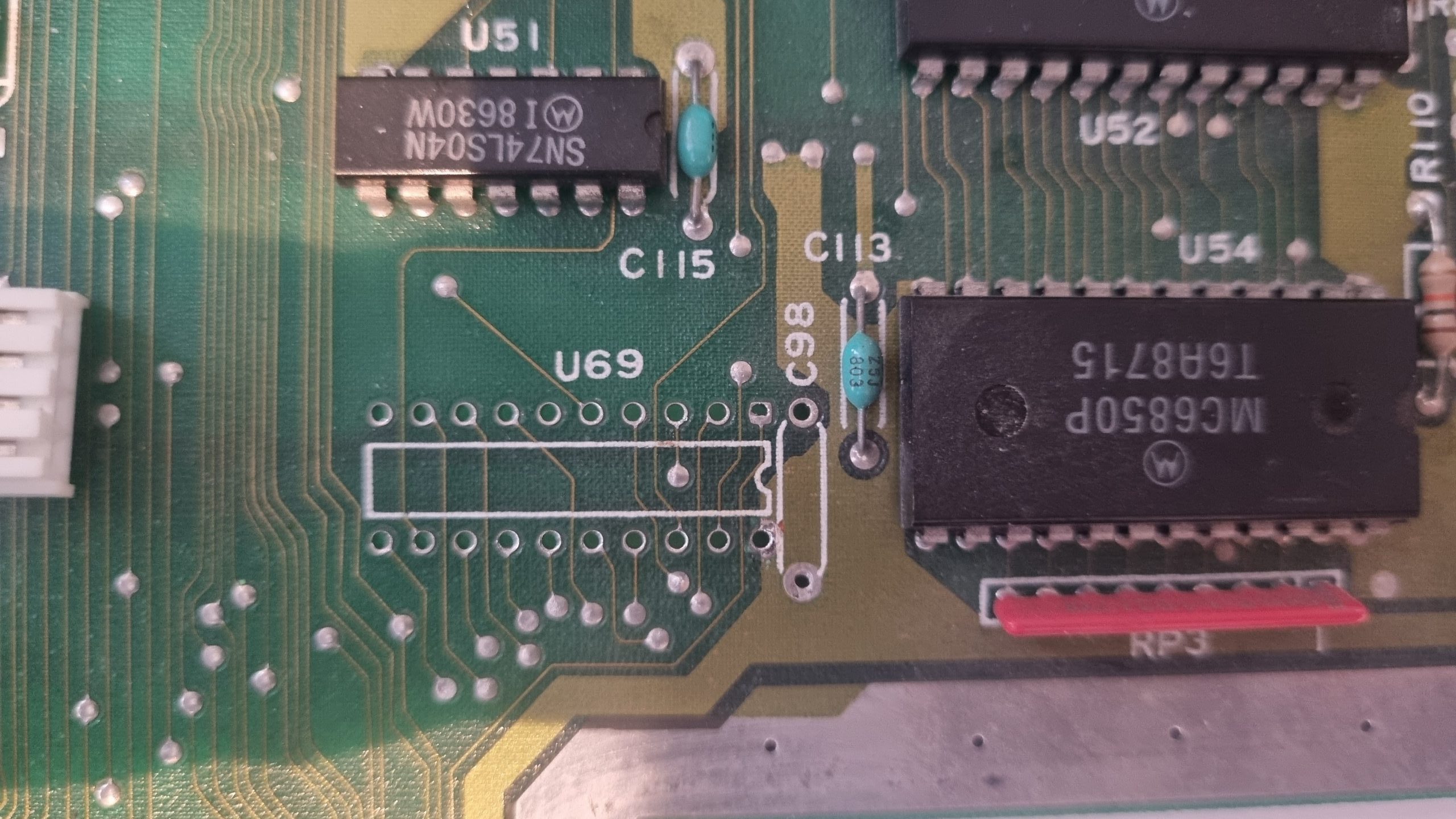
So I started to check the empty spots and silk-screen printings to the original Mega-ST schematic. All major parts are there… but where’s the RTC-PAL?
Ah, there it is. In the bottom left corner of the board, next to the two ACIAs where is also sits in a Mega-ST.
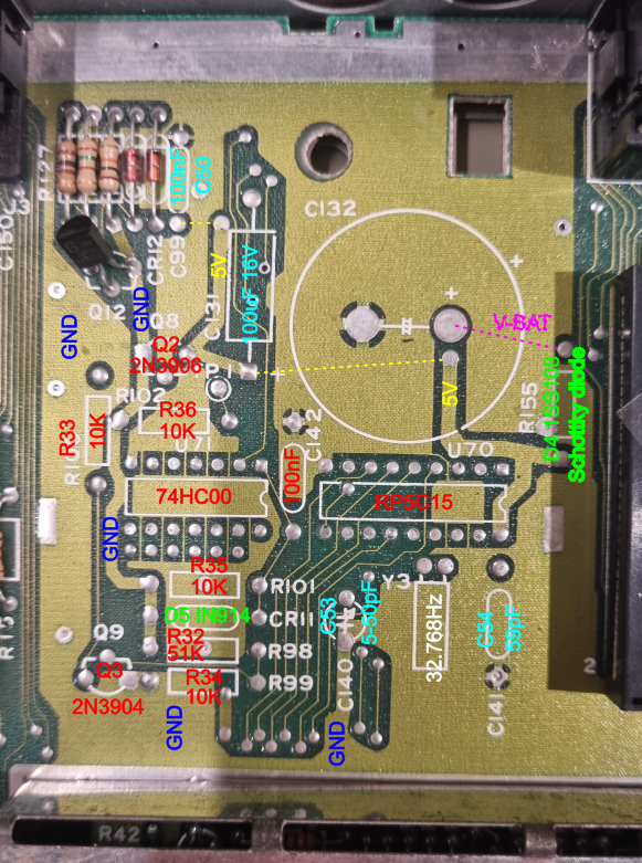
Here’s the mapping… the part-markings are different of course.
ATARI would not be ATARI if there wasn’t a mistake in the on-board markings.
“R155” is not a resistor but a Schottky diode. But everything else was more or less 1:1 Mega-ST design.
With the part name I added the marking of the original Mega-ST schematic.
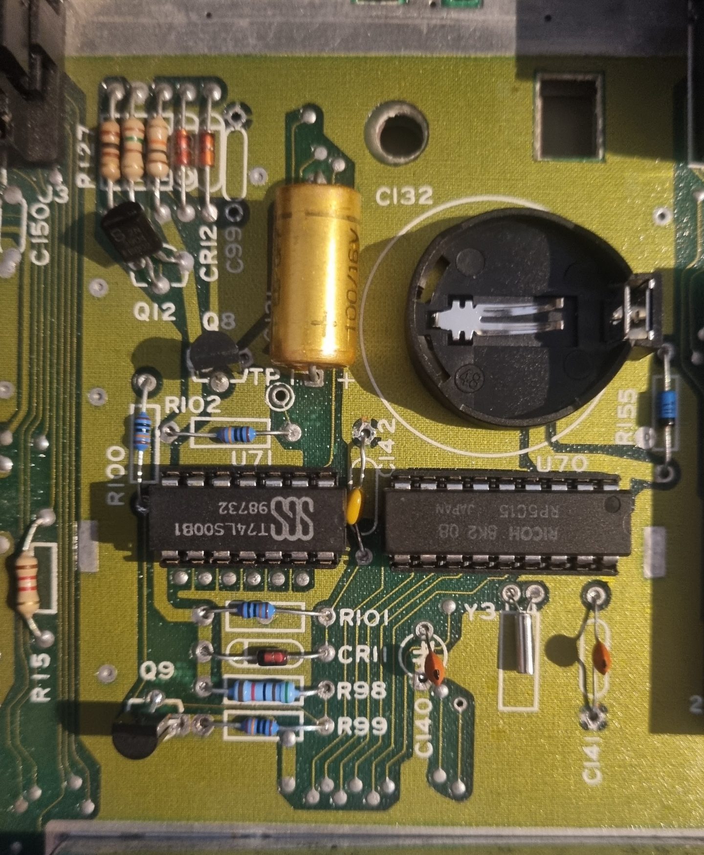
So in went the parts. The almighty internet gave me a JED file fpr the RTC-PAL and reading its specs, it was a good bet that the 32.768Hz I use needs about 22pF caps.
The coin-battery holder was meant for a bigger cell with an unusual pinout – so I mended a CR2032 to fit. All done, it looks like this:
NB: The 74LS00 was inserted for testing only. To save on battery, this has to be replaced by a 74HC00!
And the GAL (Which is a “more modern” 16V8H PALCE here):
After this – lo and behold – this prototype is even more unique.
Actually, it’s like a Mega-ST4 in a 1040ST case – RTC and Blitter included.
Next up: Clean the case and keyboard real good. But that’s boring, so no documentation here 😉
This is it. Hooray! The final Cube as I always wanted it to be.
It just took me about 2 years of planning, blood, sweat & tears, huffing and puffing. Many tries to find the right parts, plenty materials evaluated always trying to keep the budget low.
The sleeping beauty – yeah, it’s a bit snow white coffin’ish
Meet the ancestors
You might have followed the route I took for quite some time now:
It began with the ‘Tower of Power‘, basically a component carrier with a power-supply.
After some years it was replaced by the first Cube. Well, yes, while it had a somewhat cubic’ish case, is still was just a dull standard industrial case. Not really what I imagined how my computer should look.
Form follows function
If you’ve read some posts here on GeekDot, you might already got the impression that I’m a sucker for design. Well, not that kind of a surprise, given I studied design some decades ago 🙄
I’m also heavily influenced by the works and philosophy of Dieter Rams (mainly for BRAUN) and Hartmut Esslinger (of frog design), of which you might not have heard about, but you know their designs for sure…
So I fell in love with the Parsytec x’plorer and other iconic computer designs like these ‘cubistic’ examples:
The most famous Cube
Acrylic glass is never a bad choice
Connection Machine 1. 8 cubes building a cube.
Can't get more cubic than this.
Yes, I am a strong believer that a computer, while basically being a rather boring calculation tool, should look good, timeless and might give you an idea of its innards are actually doing something.
We could probably go on forever, defining how a well designed computer should look like. But like the Romans used to say: “non potest argui per gustum” (You can’t argue about taste)…
Let’s say, I’m probably not totally off, given that most designs I like are also on display at the Museum Of Modern Art 😉
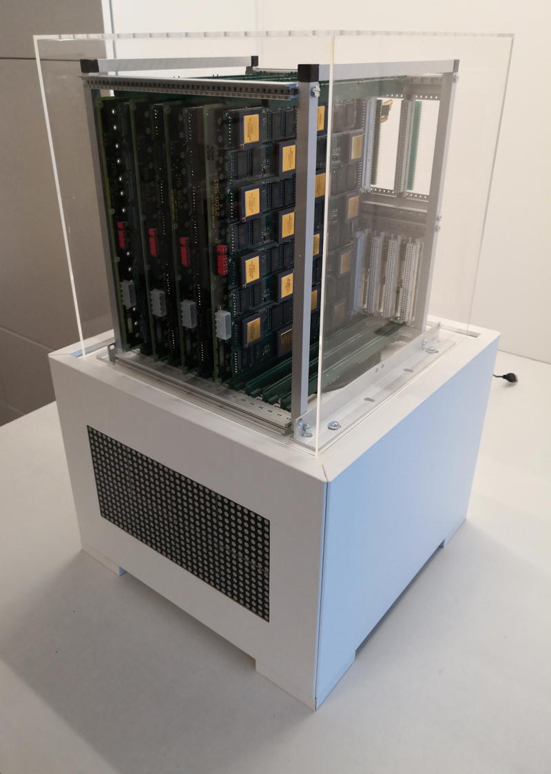
So mentioning the Final Cubes design, it’s case we’re talking about: If you’re really picky, then yes, the Final Cube is actually two cubes:
The carrier-cage on the top which I tried to keep simplistic and invisible to give the PCBs as much stage as possible. The user should be able to see the many, shining CPUs. So 10x10mm aluminum square tubes are connected by 3D-printed frame-corners to provide maximum view onto the technology.
For protection but also as a design statement and tribute to Rams’/Gugelots famous ‘snow white’s coffin‘ everything is surrounded by a 30x30x30cm translucent acrylic cube.
The white base actually isn’t cubical at all being much wider than tall. Nevertheless, its design should be even more simplistic and cautious to serve three purposes:
Give the computing-parts above it a proper podium
House the LED array which provides the fitting aura
…and finally house all the tech the user should not care about
With quite a big fan between the base and the top both work like a chimney (following the convection) sucking the air from the bottom and blowing it through 169 holes in the top plate of the cube.
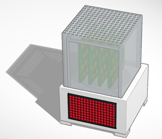
Here’s an idea out how it looks “working”:
When one thing comes to another
The parts of which the Final Cube is build from aren’t all created this year. Actually only the case and the cage-frame are from 2019 – all other parts were designed by me some years before.
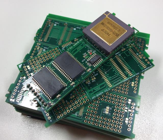
The core of everything are TRAMs – these are Transputer computing modules defined by Inmos back in 1990. The specific TRAMs used are my own AM-B404, each containing a 25MHz T800 and 2MB of fast SRAM.
Finest home-made TRAMs
16 of these TRAMs are placed onto an Inmos B012 (or compatible) carrier board. And up to 10 of these carriers can be put into the Cubes carrier-frame creating the cluster.
Under the hood
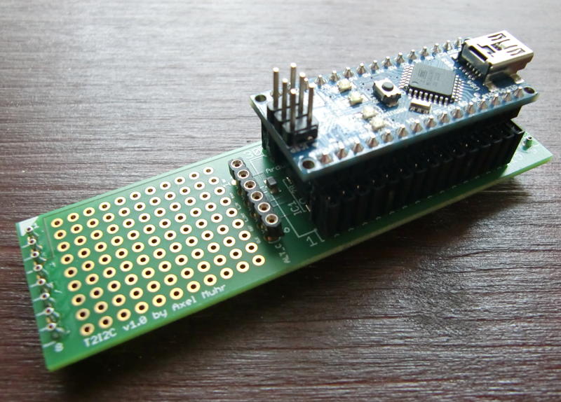
Below the carrier-frame, in the base, you can spot a 32×16 LED panel. This one is actually from 2012 when I designed the T2i2c, an i2c-bus to Transputer TRAM.
Yes, that’s an Arduino Micro on top of a TRAM
So it was a natural move to make the T2i2c into a system-controller. It does not only controls the LEDs displaying the current load of all Transputers, but also using a photo-diode to set the display brightness as well as measuring the internal temperature and overall power consumption.
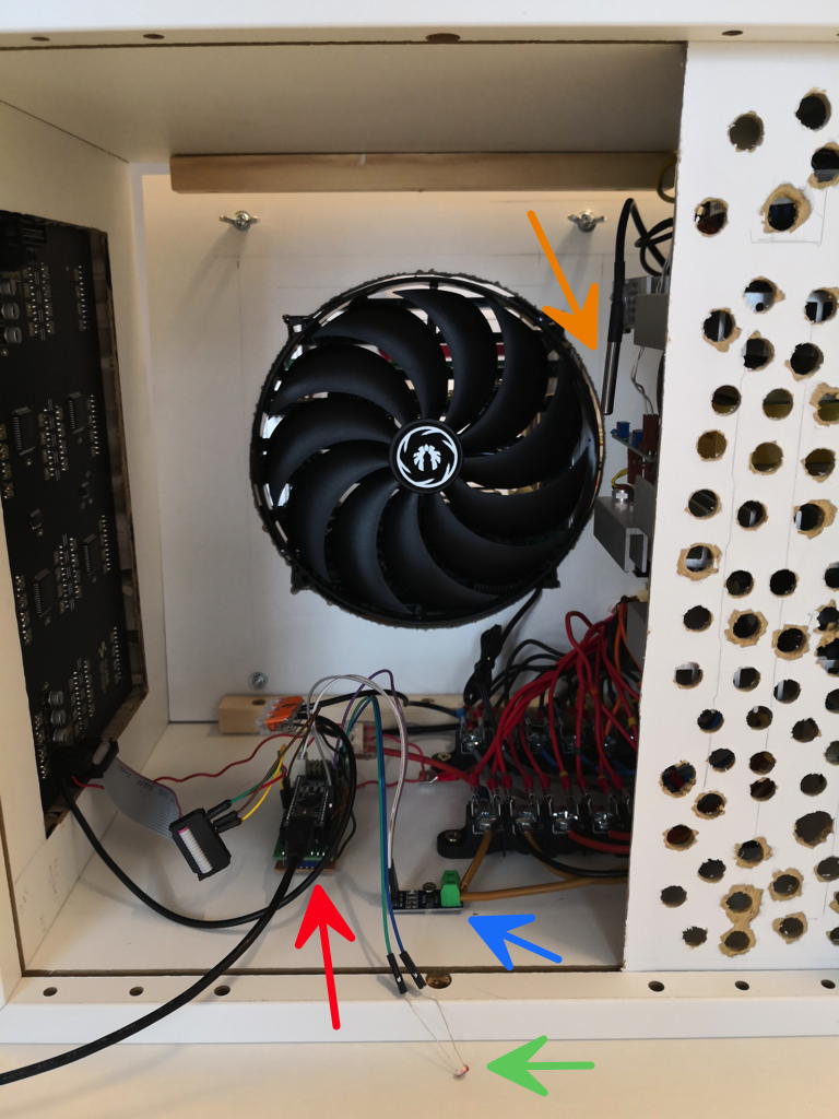
Here’s an overview of the base internals:
I know, the venting holes are not pretty – but they do their job and prevent you from accidentally touching the power-supply.
The red arrow points to the T2i2c being connected to the LED panel to the left as well as to a hall-sensor (blue arrow) measuring the power consumption, a temperature sensor (orange) and a photo-diode (green).
You cannot overlook the 22cm fan in the back sucking air from the bottom along the power-supply and pushing it up to the Transputers above to keep them cool.
And their power consumption is not to be trivialized. In average a single Transputer TRAM requires is about 1 ampere… so the math is easy. This means the quest for a powerful power-supply was on.
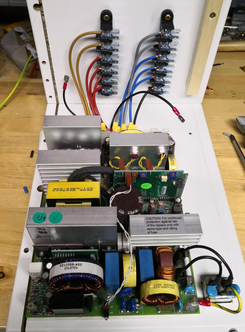
After some months I found what used to be the power-supply meant for a 3Com Corebuilder 7000: The mighty 3C37010A. A whopping 90A@5V should be OK for starters… here’s the fitting procedure:
Mooooore powerrrrrrr, Igor! You touch, you die!
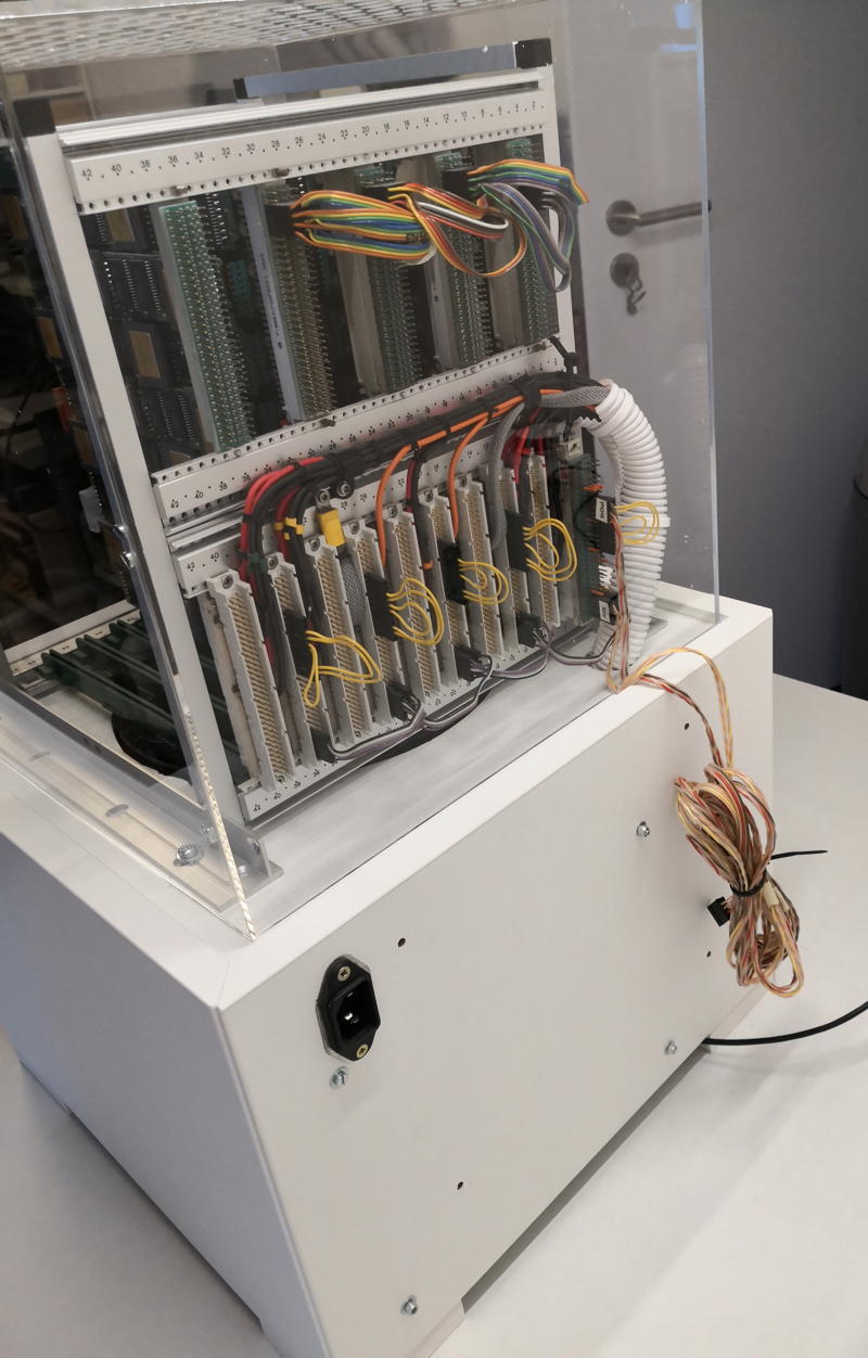
The back of the medal…
The backside did not change compared to the previous Cube back – well besides the supply-cabling which now goes down into the base instead to the side of the cage.
In consequence you’ll spot the power-connector there. No switch though – still thinking about that… as well as a nicer cable-management for the link-cable which is normally connected to the host.
Next up would be a host matching the look. Mhhhh….
home of real men's hardware
We use cookies on our website to give you the most relevant experience by remembering your preferences and repeat visits. By clicking “Accept”, you consent to the use of ALL the cookies.
This website uses cookies to improve your experience while you navigate through the website. Out of these, the cookies that are categorized as necessary are stored on your browser as they are essential for the working of basic functionalities of the website. We also use third-party cookies that help us analyze and understand how you use this website. These cookies will be stored in your browser only with your consent. You also have the option to opt-out of these cookies. But opting out of some of these cookies may affect your browsing experience.
Necessary cookies are absolutely essential for the website to function properly. This category only includes cookies that ensures basic functionalities and security features of the website. These cookies do not store any personal information.
Any cookies that may not be particularly necessary for the website to function and is used specifically to collect user personal data via analytics, ads, other embedded contents are termed as non-necessary cookies. It is mandatory to procure user consent prior to running these cookies on your website.