All posts by Axel

http://www.geekdot.com/about-me/

Transtech TMB316

The Transtech TMB316 never really seemed to see the light of day and is probably one of the last Transputer developments of AG Electronics for Transtech. Internally it’s also been called the “MTPA-0001”, MTP translates into Multi Transputer Platform, most likely “A” for 2MB and version 0001.

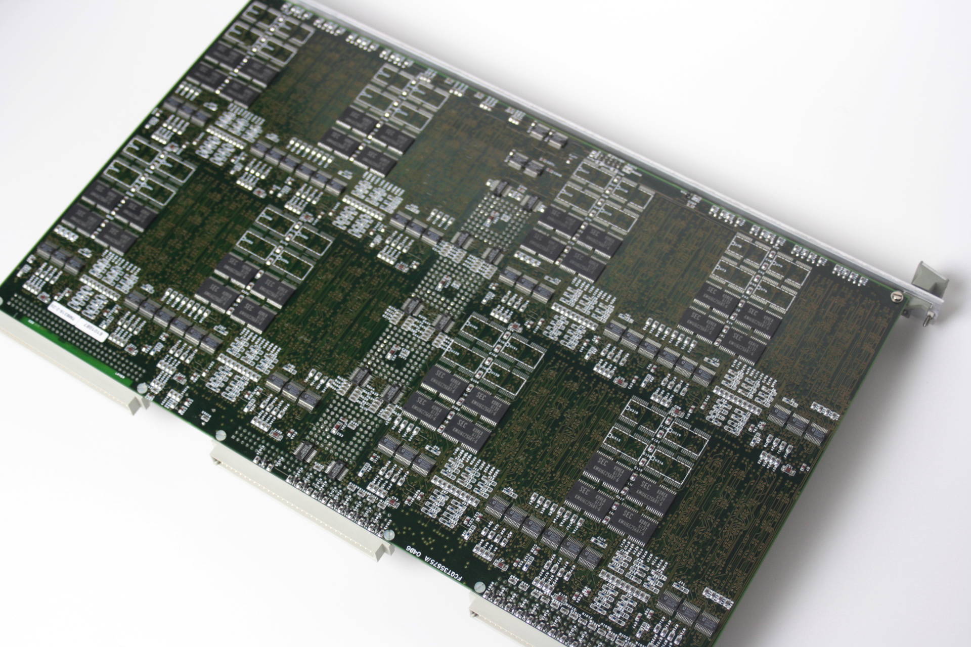
It’s a triple-height Eurocard board featuring 16 T805 at 25 or 30MHz, each with 2 or 4MB RAM. This is the card in full beauty:

TMB316_total

As you can see, it’s not totally cramped with parts and actually has quite uncongested areas. The reason for that is, that this model (Called TMB316-2-25) only uses 2MB of the possible 4MB RAM per Transputer and while all Transputers are placed on the top side of the PCB, every second Transputer has its RAM on the bottom side, right beneath the ‘free space’ visible on the top. This is the back side (flipped horizontally):

TMB316_back

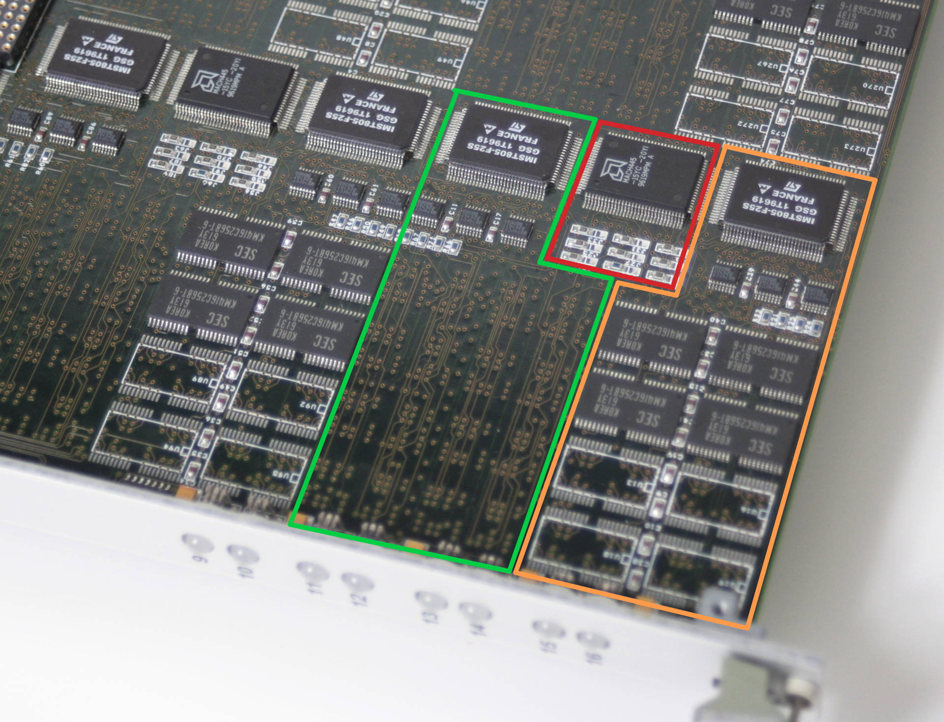
It becomes more obvious, when we zoom into a Transputer section of the board:

TMB316_nodes

I coloured each Transputer (green and orange) with its RAM area. The red area shows the CPLD which is shared between the two Trasnputers and handles the DRAM control and such.
Also visible on the cards front panel are 8 of totally 16 LEDs which display each Transputers status.

Obviously meant for a bigger systems, Transtech/AG Electronics planned the TMB316 for big deployments, i.e. more than one card. So each card uses four C004 link switches which connect the 16 T805 to each-other as well as to the outside world via the DIN connectors at the back of the card (totally non-standard pinout). This is fine if reconfiguration of the T-network is important but there’s no alternative but using dummy PCBs if all you need is speed. And being an avid GeekDot reader, you know my view on C004’s 😉

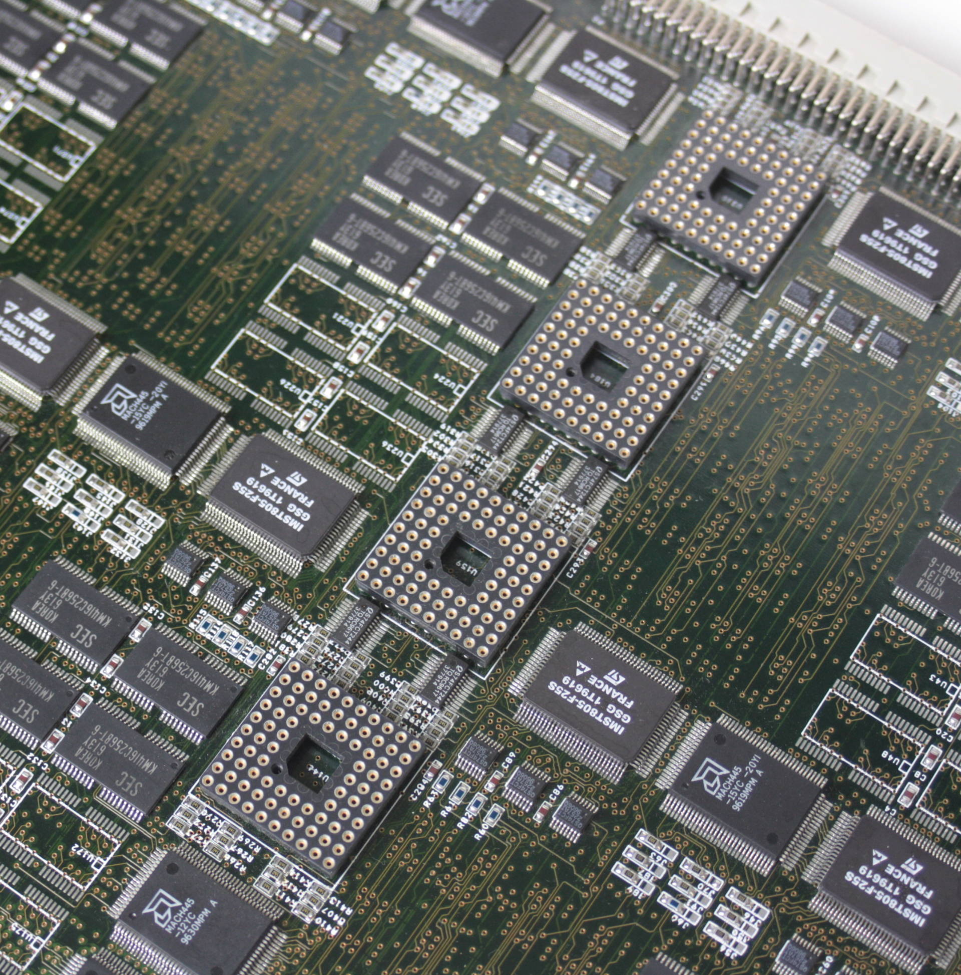
TMB316_C004This is where the C004s were meant to live.

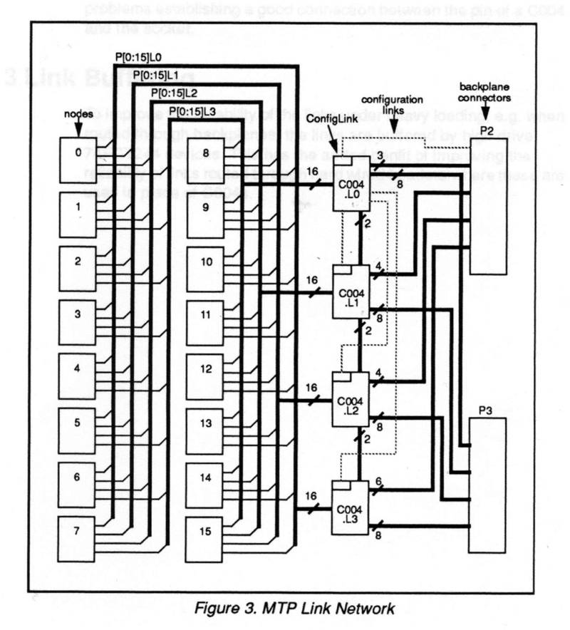
Just in case you really want to know, here’s how the Transputer nodes are connected to the 4 C004 and to the backplane connectors:

TMB316_C004_links

Basic Transputer Tools

Ok, so you have your shiny (not so) new Transputer system installed/connected and you really like to know if it works and at least see some results… you’re in need of basic Transputer tools to get started.

First, download the Geekdot “Transputer Tool Kit” from my Transputer software page (New releases are possible, mind the version number).
Each tool introduced here has its own folder in the archive.

ispy/mtest

Even it’s historically not the first application ever developed for Transputers it’s for sure one of the most used.
It started as ‘check‘ and at some point got renamed into ‘ispy‘ – whatever the name is, the technical term would be “network worm”. This means it’s a special piece of code which a) sniffs around in a transputer (what kind, number of links and their speed) and b) replicates itself over all links it previously found.
When done, it outputs a network map like this example:

Using 150 ispy 3.23
 # Part rate Link# [ Link0 Link1 Link2 Link3 ] by Andy!
 0 T800d-25 292k 0 [ HOST   ...   ...   1:0  ]
 1 T425c-20 1.6M 0 [  0:3   2:0   3:0   ...  ]
 2 T400c-20 1.8M 0 [  1:1   ...   ...   ...  ]
 3 T400c-20 1.7M 0 [  1:2   ...   ...   ...  ]

ispy is used on geekdot.com extensively, so any time I write about Transputers you will see some sort of ispy output for sure.
There are several versions of ispy included in this kit. This is because some versions behave more stable than other in certain circumstances. E.g. the most recent version 3.23 does not work very well with the C004 link-switches.

“The other part” of ispy is called mtest. mtest takes ispys output and runs an indepth memory test/report on all Transputers found.

iserver

iserver is part of what INMOS called “itools” – long before Apple discovered the “i” for themselves 😉 – there were many others, mainly development focused (e.g. idebug, icconf etc.).
It is more or less the successor to the godfather of all Transputer booting tools “afserver” (1988). Well, it has to be, being the on INMOS supplied with all their other tools and languages.
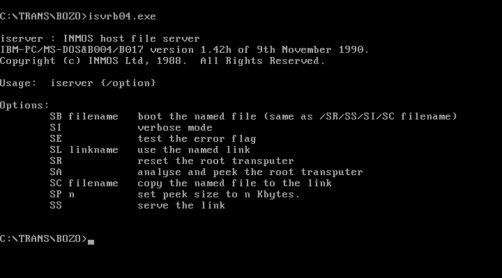
The possible options are quite self-explanatory and printed to stdout when omitting any option:

iserver142h

Basically if you see a *.btl, *.b4 or *.b8 file it’s most likely meant to be executed with iserver. Before running successfully iserver need some environment variables set to successfully to be used:

set IBOARDSIZE=#100000
set TRANSPUTER=#150

These two settings tell all itools how much RAM the Transputer has to work with and at which port address it can be found (0x150 is default anyway). The archive contains V1.42h from Nov. 1990 which is the most recent as far as I know.

Mandelbrot

The “CSA Mandelzoom Version” is one of my favorite benchmark tools. I like it so much, that I run it once a while just for fun.. and to extend my benchmark table which I’ve collected over the time using it.

It is nice because it features integer (T4xx) as well as floating point (T8xx) versions of the calculation ‘slave processes’ and scans the network itself. No external tool needed. It’s also possible to let the host (i.e. your PC) calculate the Mandelbrot fractal to get an idea, how much faster/slower your Transputer network is – the archive contains a little benchmark result text file which I accumulated over the years.
Also there are some handy switches available (‘-h’ for help):

  • -v : Use VGA graphics
  • -t : Run on host instead of Transputers
  • -a : Autozoom, loads  a list of coordinates from man.dat and start calculating them without manual interaction.
  • -b : Use a different base address (instead 0x150)
  • -x : Verbose output of the Transputer initialization process (added by me)

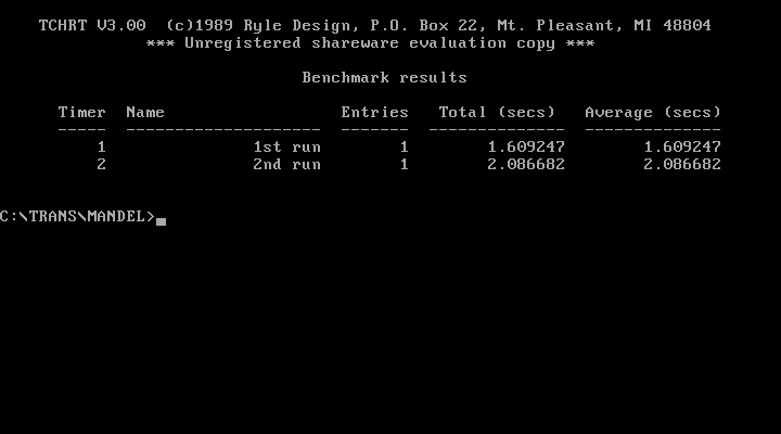
After a while I got tired of manually time a calculation run and also ran into problems with large networks which simply became to fast to hand time. So I extended the code of Mandelzoom with a high precision timer (TCHRT, shareware, can’t remove the splashscreen, sorry) which prints out a timer summary when run with the “-a” parameter. I provided my default “MAN.DAT” file, which contains 2 coordinates to calculate (1st & 2nd run) and used for all my benchmarks.

csa_mandel_timerThese are the results of my DOS host system running in VirtualBox.

Caveat: It breaks if there’s a T2xx in the network (e.g. B008/B012) 🙁 And as always: Read the F-ing README.txt!

Since I started to heavily modifying the source, I wrote a post of its own about it as well as put everything on github, so you can join the fun 😉

Other Tools

iskip

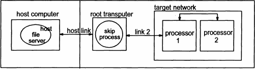
iskip can be very handy, when ‘talking’ directly to (externally) connected links, e.g. another network which is connected to your root Transputer. Here’s a good example:
You like to put code directly onto “processor 1” which is connected to link 2 of your root Transputer:

iskip

So you call

iskip 2 /r /e

This sets up the system to direct the program to the target network over the top of the root transputer and starts the route-through process on the root transputer. Options ‘R’ and ‘E’ respectively reset the target network and direct the host file server to monitor the halt-on-errorflag. The program can then be loaded ‘through’ the root Transputer directly onto processor 1 using:

iserver /ss /se /sc test.btl

debug.exe

Yes, I do mean the comes-with-DOS debug.exe. Well, you can use any debugger you like as long it can read/write to port addresses.
Obviously this means [MS|PC|Open|Free]DOS only. You won’t get far with this on Linux, any Windows or OS/2. At least for initial debugging and testing I strongly recommend to use the “bloated interrupt manager” known as DOS.
First of all, you have to know the port addresses the C012 registers are mapped to . There’s a de-facto industry standard which INMOS introduced with the IMSB004. Its been adopted by 90% of all 3rd party products, even with certain ISDN cards using Transputes.

The base address normally is at 0x150 (which can be configured to other addresses in some cases). From this base adress the offset is always the same:

Base Adress Register Comment
+0x00 C012 input data  read
+0x01 C012 Output data write
+0x02 C012 input status register read = returns input status
write = set input interrupt on/off
+0x03 C012 Output status register read = returns output status
write = set output interrupt on/off
+0x10 Reset/Error register write: Reset Transputer & C012 and possibly subsystem (check manual)
read: Get Error status
+0x11 Analyse register  (un)set analyse

So here’s a clean Transputer setup ‘conversation’ using debug (comments are just for clarity, not supported in debug):

c:\>debug
 -o 160 1         # Assert RESET
 -o 161 0         # Deassert ANALYSE
 -o 160 0         # Deassert RESET ... init B004/IMSC
 -o 152 0         # Clear Input  Interrupt enable
 -o 153 0         # Clear Output Interrupt enable
 -i 152           # Read Input Status
 00               # Bit 0 = 0 -> no Data waiting
 -i 153           # Read Output Status
 01               # Bit 0 = 1 -> ready to send 
 -i 160           # Read Error
 00               # Bit 0 = 0 -> ERROR not signaled
-o 151 1          # send POKE
-i 153            # Read Output Status
01                # Ready -> POKE Ack (00 = BAD no Transputer) 
After that you’re fine to send and receive bytes through 0x151/0x150. Doing so, you’re completely free which programming language to use. Here are some examples in AppleSoft Basic or even Python.

Upgrading the NumberSmasher

After a long time, I had a look at my 3 NumberSmashers again. Looking closer, I spotted a difference.
One had a silkscreen print saying “V1.2” while the others were “V1.1”. So why not upgrading the NumberSmasher yourself?!

Step 1

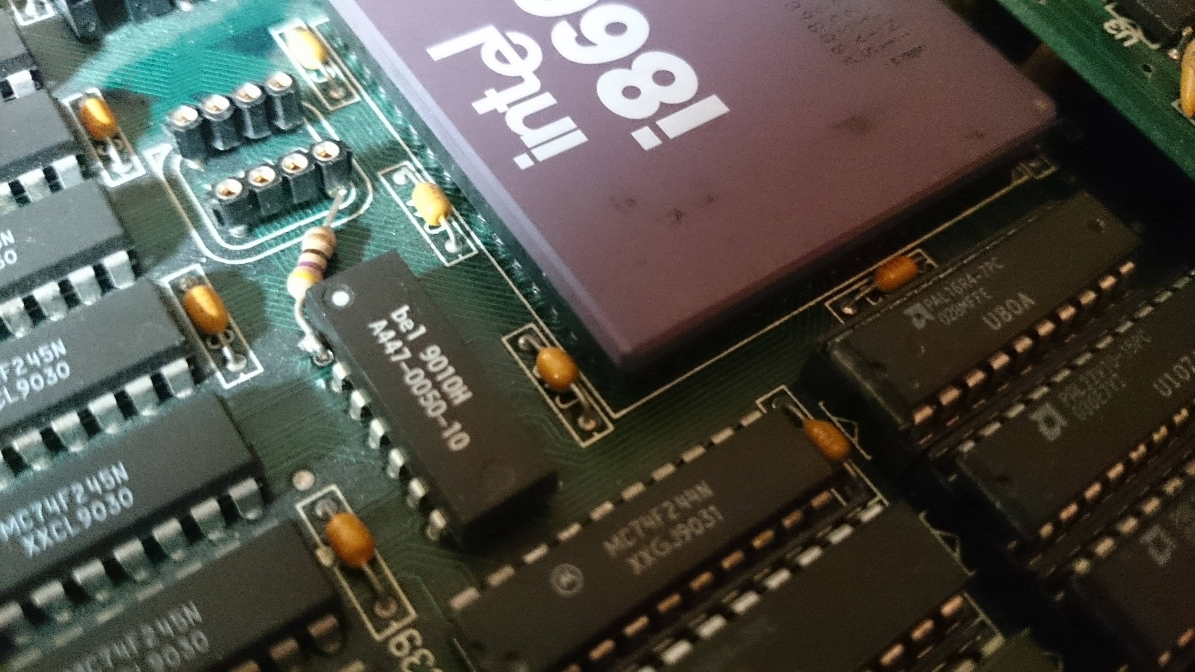
The most obvious fix the V1.2 had was a 47ohm resistor fitted between one pin of the 40MHz oscillator and pin-1 of an IC called “A447-0050-10 “. That’s a “10 tap leading edge delay module” made by Bel Fuse Inc.. Pin 1 takes the input signal and each other pin  adds a delay of 5ns.
So I assume this fix was meant to reduce noise on the delay chip input to make its output cleaner.

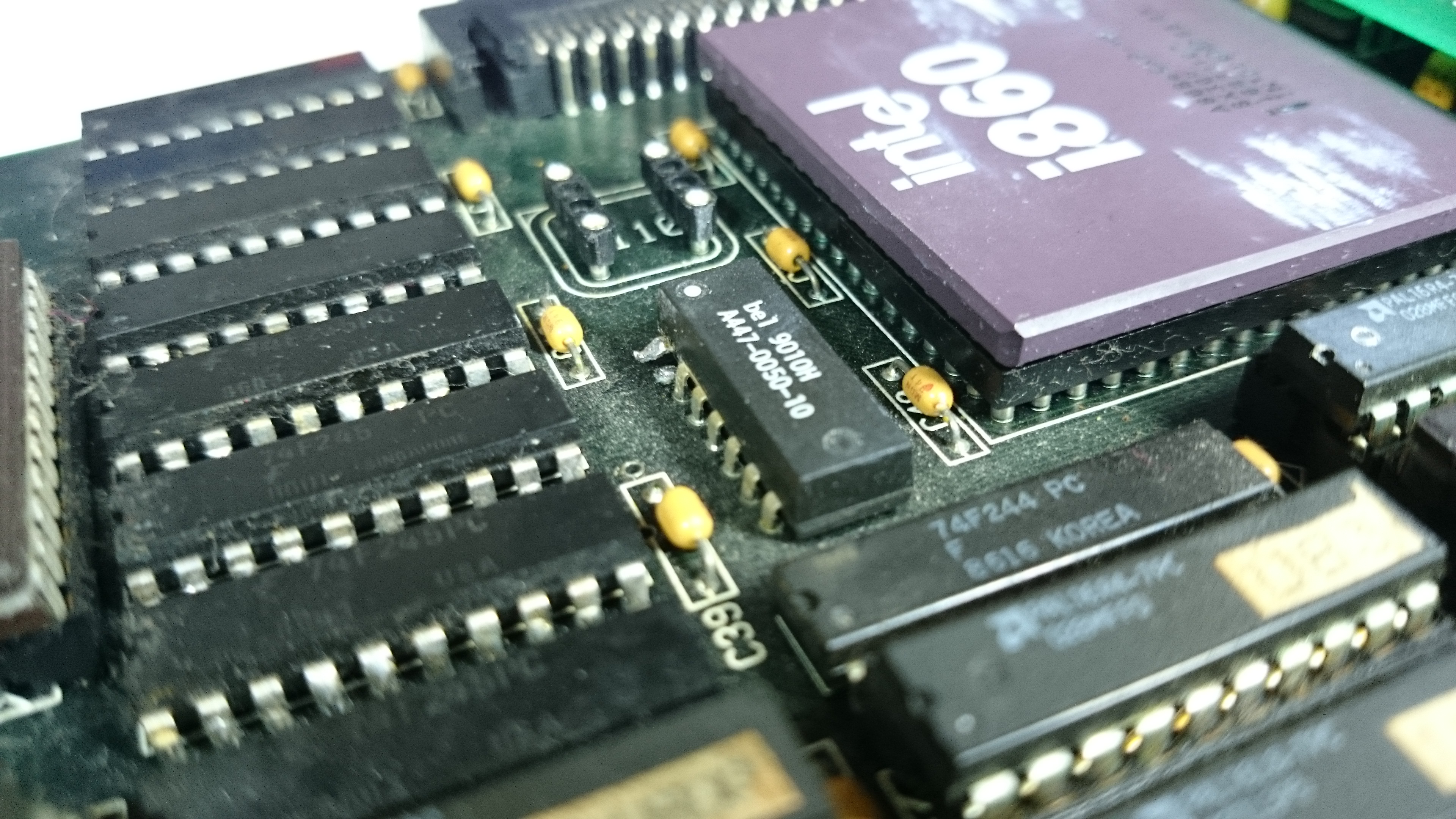
Anyhoo, here’s the quick and easy howto. The below picture shows the section of a NumberCruncher V1.1. near the almighty i860. Next to it is the (now empty) socket for the 40MHz oscillator. Next to that you see the 10-pin delay chip which pin-1 already had been cut and slightly bent upwards.
We need a bit of pin-1s leg so when cutting it, be sure to cut it as close to the board as possible!

NS_premod.jpeg

Now for the next step. Get a 47ohm resistor and shorten its wires to bridge the space between the bent leg of the delay chip and the output pin of the oscillator (see below picture).

NS_860_postmod.jpeg

To make things perfectly clean, remove the pin remains by flipping the NS860 over and pull the remains with your solder iron and tweezers.

Step 2

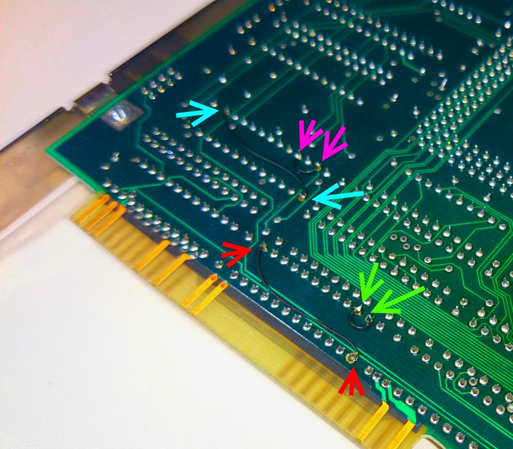
I thought this would be a simple fix, too. There are some retrofitted jumper-wires on the back of the NumberSmasher near the ISA connectors.

NS860_patchwiresI’ve color adjusted the photo to make the wires more visible. Colored arrows show start and end of each wire

But taking a look at the chips those jumper-wires are connected, it showed that the two PAL22V10  of the V1.1 board were replaced by two PALCE610H – which is a completely different beast, same number of pins, everything else varies:

max in max out macrocells Specials
PAL22V10 22 20 10
PALCE610H 20 16 16  D, T, J-K or S-R Flip_Flops, counters and large state machines possible

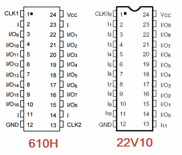
Additionally here’s a side-by-side of the pinouts. This immediately explains the two long jump-wires from pin-1 to pin-13 (red & blue arrows) which connect the two clock inputs.

20v10_610h

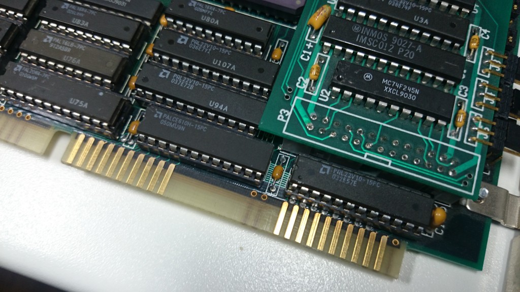
Here’s the PALCE610 in place:

PALCE610It’s the one at the bottom in the middle (named U93) and one hidden beneath the link-interface board (U-88).

My assumption is, that the PALCE610 has a completely different programming and the jump-wires just support the changes made, i.e routing the outputs of pin3 to input pin2 (green) respectively pin4 to pin 2 (pink) .

Next up: I will get out my Über-Programmer and try reading it – but I have low hopes, as MicroWay normally set the protection fuse on all the GALs/PALs they used.

Update

Wow, that was unexpected. Both PALCE610 hadn’t had the protection fuse set – at least on my retro-fitted V1.1 board. So lo-and-behold, here are the JEDEC files for you to program your own PALCEs!  And because I couldn’t resist, I’ve disassembled the JEDs and added the PALASM code in the archive, too 😀

That said… it’s completely unclear what had been changed from V1.1 to V1.2 (well, U93 being close to the ISA connector gives a hint) and under which circumstances an upgrade is necessary at all.
But if you own a 1.1 and it behaves strange, you should give it a try.

Nostalgia

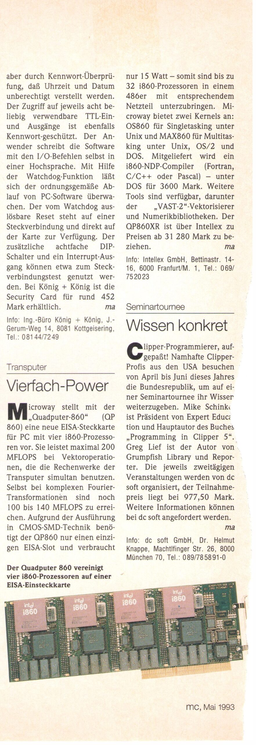
After the NumberSmasher, MicroWay presented the “QuadPuter”, an EISA-Bus based quad-i860 monster… which had a short lifespan and was, well, expensive as expected. 31000 German Marks was exactly what you would have payed for an Volkswagen Golf mkII GTI 16V back then… one of the hottest hot-hatches you could get.

I found this snippet in one of my (German) computer magazines (“MC”, 1993) – they mention the OS860 (for DOS) as well as the MAX860 multiuser-OS for UNIX, OS/2 and DOS:

The Inmos C004

Hardware

Before I reinvent the wheel, here’s the quick intro from the manual, what an Inmos C004 actually is:

The IMS C004 is a transparent programmable link switch designed to provide a full crossbar switch between 32 link inputs and 32 link outputs. The IMS C004 will switch links running at either the standard speed of 10 Mbits/sec or at the higher speed of 20 Mbits/sec.
It introduces, on average, only a 1.75 bit time delay on the signal. Link switches can be cascaded to any depth without loss of signal integrity and can be used to construct reconfigurable networks of arbitrary size. The switch is programmed via a separate serial link called the configuration link.

So in simple words: 32 inputs can be freely connected to 32 outputs. Great for large Transputer networks which can be reconfigured only by reprogramming the C004 – on top of that, you can cascade them and create huge, complex networks to make any connection imaginable possible. Like those Parsytec used in their SuperCluster machines looking like this:
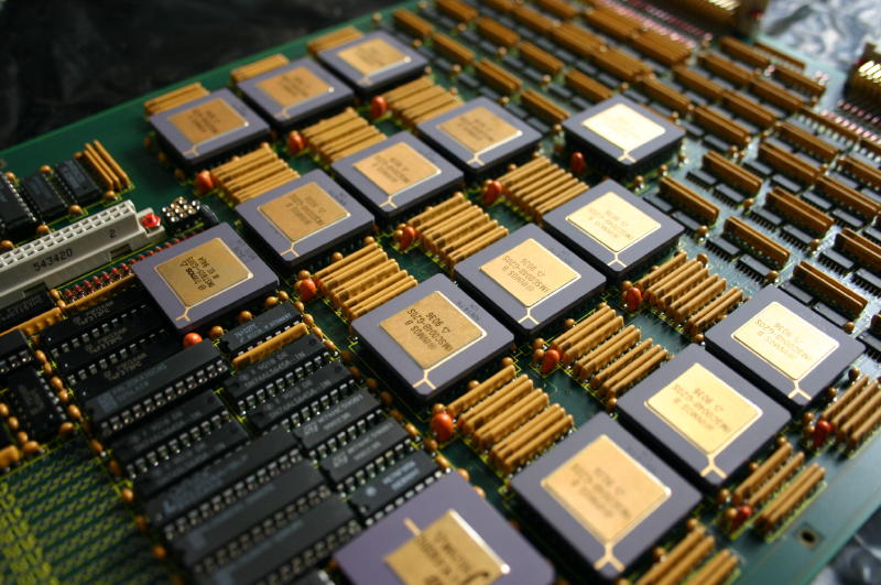
MegaFrameXbarDetailYes, that’s 13 C004s and one Transputer to rule them all…

… so much for the theory.

In practice, the C004 is a bitch. Not only does it require a Transputer to configure it (normally a 16bit T2xx) it also adds quite a delay into the link-communication. As mentioned above, it’s “only a 1.75 bit time delay” but this can sum up to quite an amount.
Let me quote some more realistic numbers from the Helios manual (pp.255):

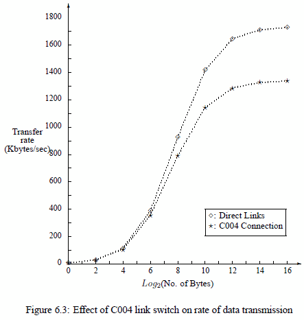
It is of interest to ascertain the effect of the Inmos C004 on the performance of the Helios communication mechanisms. Figure 6.3 illustrates the rates of data communication (Kbytes/second) attained using message passing primitives (PutMsg() and GetMsg()) between two Transputers that were
1. Directly linked and
2. Connected through a C004 link switch.
It is evident from Figure 6.3 that the effect of the C004 link switch on the rate of communication is far from negligible. The overhead imposed by the link switch increases with the size of the message. In the worst case (64 Kbyte message), transmission through the C004 is 23 % slower than sending data over directly connected links.
C004_helios

Oops. 23% is quite essential. So before planning to set up a crazy C004 network you might consider what you want to achieve.
Is it for educational network studies only? Fine.
Are you going for speed and rarely change your Transputer network configuration? Avoid it!

IMHO even the 10 possible Transputers on an IMSB008 do not require a C004 making your day.
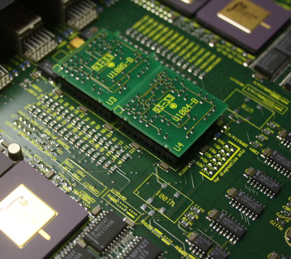
Actually, even Parsytec thought that this is useless to use a link switch for the 16 Transputers in their beautiful x’plorer and replaced it by hard-wire dummies:
C004_dummies2

Configuration

Ok, you’re still not scared away and really do like to know how to handle that beast. Fine, here’s what I went through:

To work with a C004 you obviously need either a TRAM carrier like the B008 or some sort of motherboard like the IMSB012 or IMSB014.  Read the boards manual to understand how to connect to the T2xx Network Control Processor (NCP).
For example the IMSB012 has extra pins for “config down” (i.e. IN) and “config up” (i.e. OUT) for its T212 and any other boards being chained to it.
As for the IMSB008 has its T222 connected to Link 1 of TRAM 0.

The hardware wiring is important to know, because this information is needed for the so-called hardwire file used by the INMOS tool “MMS2” (Module Motherboard Software, MSDOS only, the manual is available here).
After reading the manual (do!) you should be able to read this hardwire file for an B008 quite easily. It describes the complete hardware setup and all physical connection between the C004(s), T2xx and Transputer/TRAM links on the board:

-- B008 hardwire description
DEF B008
  SIZES
    T2 1
    C4 1
    SLOT 10
    EDGE 10
   END
   T2CHAIN
     T2 0, LINK 3 C4 0
   END
   HARDWIRE
     SLOT 0,LINK 2 TO SLOT 1,LINK 1
     SLOT 1,LINK 2 TO SLOT 2,LINK 1
     SLOT 2,LINK 2 TO SLOT 3,LINK 1
     SLOT 3,LINK 2 TO SLOT 4,LINK 1
     SLOT 4,LINK 2 TO SLOT 5,LINK 1
     SLOT 5,LINK 2 TO SLOT 6,LINK 1
     SLOT 6,LINK 2 TO SLOT 7,LINK 1
     SLOT 7,LINK 2 TO SLOT 8,LINK 1
     SLOT 8,LINK 2 TO SLOT 9,LINK 1
     C4 0,LINK 10 TO SLOT 0,LINK 3
     C4 0,LINK 1 TO SLOT 1,LINK 0
     C4 0,LINK 11 TO SLOT 1,LINK 3
     C4 0,LINK 2 TO SLOT 2,LINK 0
     C4 0,LINK 12 TO SLOT 2,LINK 3
     C4 0,LINK 3 TO SLOT 3,LINK 0
     C4 0,LINK 13 TO SLOT 3,LINK 3
     C4 0,LINK 4 TO SLOT 4,LINK 0
     C4 0,LINK 14 TO SLOT 4,LINK 3
     C4 0,LINK 5 TO SLOT 5,LINK 0
     C4 0,LINK 15 TO SLOT 5,LINK 3
     C4 0,LINK 6 TO SLOT 6,LINK 0
     C4 0,LINK 16 TO SLOT 6,LINK 3
     C4 0,LINK 7 TO SLOT 7,LINK 0
     C4 0,LINK 17 TO SLOT 7,LINK 3
     C4 0,LINK 8 TO SLOT 8,LINK 0
     C4 0,LINK 18 TO SLOT 8,LINK 3
     C4 0,LINK 9 TO SLOT 9,LINK 0
     C4 0,LINK 19 TO SLOT 9,LINK 3
     C4 0,LINK 20 TO EDGE 0
     C4 0,LINK 21 TO EDGE 1
     C4 0,LINK 22 TO EDGE 2
     C4 0,LINK 23 TO EDGE 3
     C4 0,LINK 24 TO EDGE 4
     C4 0,LINK 25 TO EDGE 5
     C4 0,LINK 26 TO EDGE 6
     C4 0,LINK 27 TO EDGE 7
 -- Uncomment the next two lines if the
 -- patch header wiring is used to
 -- connect C004, link 28 to PatchLink0,
 -- and C004, link 29 to PatchLink1.
 -- C4 0,LINK 28 TO EDGE 8
 -- C4 0,LINK 29 TO EDGE 9
   END
PIPE B008 END

After that’s done, you can prepare a second file. The so called “softwire file” which actually tells the T2xx how to internally connect his in- and out-links. A very simple example would be:

SOFTWIRE 
PIPE 0
 SLOT 0,3 TO SLOT 1,3 
END

This would connect TRAM-0’s 3rd link to TRAM-1’s 3rd link.
Now that you have the necessary config files let’s move on to the MMS itself.

Software

As with nearly every software from INMOS the MMS too is written in OCCAM and therefore has to run on a Transputer. This might be the one in TRAM slot 0 on your B008 or on a local ISA board which itself is connected with 2 links to a B012 (one for config and one to the Transputer network).

To make things easier, I prepared a complete MMS archive to download here (links to my Transputer Software page).
It contains some example soft- and hardwire files, an ISERVER.EXE (the program you need to upload code into your Transputer) as well as a batch file to easily start MMS (RUN_MMS.BAT).
Also you will find a folder with INMOS’ pimped version of ANSI.SYS called BANSI (“Better ANSI”), because all INMOS tools make heavy use of ANSI screen control. So put that into your CONFIG.SYS.

Before we begin, let’s have a look at my IMSB012 with ispy:

ispy 2.33
   # Part rate Mb Bt [  Link0  Link1  Link2  Link3 ]
   0 T800d-25 0.37 0 [   HOST    1:1    2:1    ... ]
   1 T2   -20 1.64 1 [    ...    0:1    ...    ... ]
   2 T800d-25 1.75 1 [    ...    0:2    3:1    ... ]
   3 T800d-25 1.77 1 [    ...    2:2    4:1    ... ]
   4 T800d-25 1.77 1 [    ...    3:2    5:1    ... ]
   5 T800d-25 1.75 1 [    ...    4:2    6:1    ... ]
   6 T800d-25 1.75 1 [    ...    5:2    7:1    ... ]
   7 T800d-25 1.75 1 [    ...    6:2    8:1    ... ]
   8 T800d-25 1.75 1 [    ...    7:2    9:1    ... ]
   9 T800d-25 1.75 1 [    ...    8:2   10:1    ... ]
  10 T800d-25 1.75 1 [    ...    9:2   11:1    ... ]
  11 T800d-25 1.75 1 [    ...   10:2   12:1    ... ]
  12 T800d-25 1.75 1 [    ...   11:2   13:1    ... ]
  13 T800d-25 1.77 1 [    ...   12:2   14:1    ... ]
  14 T800d-25 1.77 1 [    ...   13:2   15:1    ... ]
  15 T800d-25 1.75 1 [    ...   14:2   16:1    ... ]
  16 T800d-25 1.77 1 [    ...   15:2   17:1    ... ]
  17 T800d-25 1.77 1 [    ...   16:2    ...    ... ]

Ok, let’s start MMS2. Use/modify the batch “run_mms.bat” which will do all environment variables expected by iserver.exe and also adds the input and output files – change it as you please.
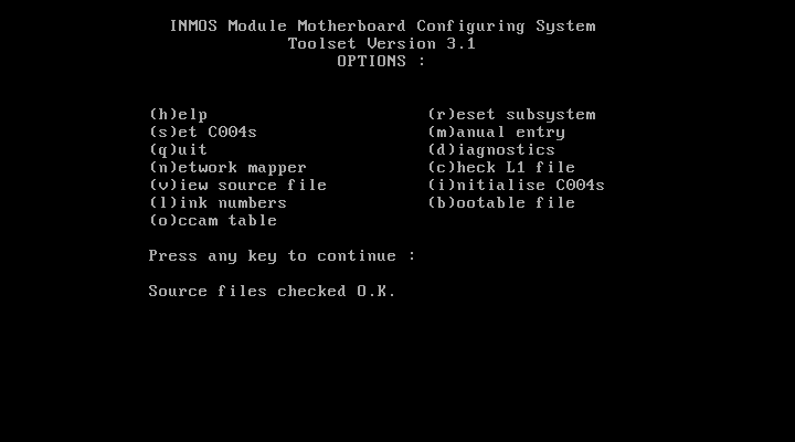
If everything works fine, iserver loads MMS2.B4 onto your Transputer and executes it. Your screen should look like the screenshot below.
First, I suggest you press “c” for checking the consistency of your hard/softwire files – if everything’s fine, MMS2 will print “Source files checked O.K.” as seen in the lowest line in the screenshot.
MMS1

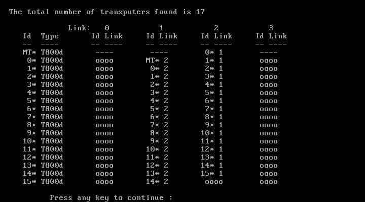
Just for the fun of it, you can try MMS’ very own network worm – so press “n” to start the network mapper. You will see that it is much slower than e.g. ispy, so just be patient.
After some seconds, you should get something like this:
MMS2

Now it’s time to program you network. So press “s” to set the C004(s). Some infos will rush trough the bottom line of the screen and finally MMS2 states “C004 setting preformed O.K.“:
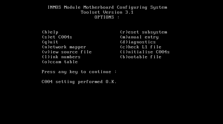
MMS3

Nothing more to do here so press “q” to quit MMS2.  (Do not run the network mapper again! It seems to reset the T2 and in my case reproducibly crashes the network).
It’s better to use ispy. ispy v2.33 to be precise. I encountered several issues with the C004 and the most recent version 3.23 of ispy.

So running ispy including the /C4  switch to display the settings of the two C004s now shows this – mind all the new connections of each Transputers Link0 and 3:

ispy 2.33
   # Part rate Mb Bt [  Link0  Link1  Link2  Link3 ]
   0 T800d-25 0.37 0 [   HOST    1:1    4:1    ... ]
   1 T2   -20 1.74 1 [    2:C    0:1    ...    3:C ]
   2 C004b   [ 6S3JM54V --U8-1C- -G--F9-I T--7-PQ- ]
   3 C004b   [ -D-2650R BL--E--K H-N3--4- -TU-1OA7 ]
   4 T800d-25 1.65 1 [    ...    0:2    5:1    6:0 ]
   5 T800d-25 1.75 1 [    ...    4:2    7:1    8:0 ]
   6 T800d-25 1.41 0 [    4:3    9:2    8:1   10:0 ]
   7 T800d-25 1.75 1 [    ...    5:2    9:1   11:0 ]
   8 T800d-25 1.41 0 [    5:3    6:2   11:1   12:0 ]
   9 T800d-25 1.75 2 [    ...    7:2    6:1   13:0 ]
  10 T800d-25 1.35 0 [    6:3   13:2   12:1   14:0 ]
  11 T800d-25 1.41 0 [    7:3    8:2   13:1   15:0 ]
  12 T800d-25 1.42 0 [    8:3   10:2   15:1   16:0 ]
  13 T800d-25 1.32 0 [    9:3   11:2   10:1   17:0 ]
  14 T800d-25 1.35 0 [   10:3   17:2   16:1    ... ]
  15 T800d-25 1.41 0 [   11:3   12:2   17:1   18:0 ]
  16 T800d-25 1.33 0 [   12:3   14:2   18:1    ... ]
  17 T800d-25 1.32 0 [   13:3   15:2   14:1   19:0 ]
  18 T800d-25 1.35 0 [   15:3   16:2   19:1    ... ]
  19 T800d-25 1.32 0 [   17:3   18:2    ...    ... ]

Yay! It worked. Positively as well as negatively.
Besides the new connections you might also spot a difference in the link-speed column. In our first run of ispy all Transputers had a link-speed around 1.75MBps.  Now it varies between 1.75 and 1.32, depending on how often the ispy worm crossed a C004.

Two final hints:

If your C004 network has been set-up as planned, you can use ispys output to programm the network later.
Just save the output into an ASCII file (ispy /c4 > my_net.txt) and when needed feed it back into ispy like this:
 ispy /r /cr < my_net.txt
This will reset the network and read in the configuration from stdin.
Obviously you can also manually edit the text file, the c4 lines

   2 C004b   [ 6S3JM54V --U8-1C- -G--F9-I T--7-PQ- ]
   3 C004b   [ -D-2650R BL--E--K H-N3--4- -TU-1OA7 ]

which isn’t as comfortable and comprehensible as editing a hard/softwire file. But your mileage my vary.

Alternatively, MMS2 can create a bootable file with your network settings. This can be used for quickly setting-up your system.
Just hit the “b” key and enter a filename. My MMS2 archive contains the above example as “BOOTB012.BTL”. Run it with “iserver /SB bootb012.btl“.

Caveats

Mind your reset! This means, in many cases a root Transputer might reset all the “worker Transputers” but also your T2xx and in effect all C004. So be careful when resetting your system.

Yes, theoretically you can reconfigure your Inmos C004 on the fly while all connected Transputer run. The most prominent example is having one network topology during data acquisition while changing it for number crunching later on.
This requires a very good knowledge of the notwork and thorough process locking etc.


Compaq RiLOe

This is a very lame page about the first Compaq RiLOe  (Remote Inside Lights Out Edition) card, the first version i.e. i960/66Mhz & Ati Rage IIC… because you can get it for cheap it can be considered a poor-mans IPMI.
I had the page hanging around on my server for years and moved it here for completeness. As it is getting vintage by now, it actually fits 😉 Under construction. Forever.
There are better pages out there, so I only provide additional info/stuff.

Software

You can get the manual here

The most recent (and last) firmware 2.53, which also resets (unknown) passwords is available here – NB: This is a MSDOS instsaller and needs two 1.44MB floppies.

Here’s an RPM, which writes the SNMP packets of the RILOE into the syslog.  Here’s the README.

Hardware

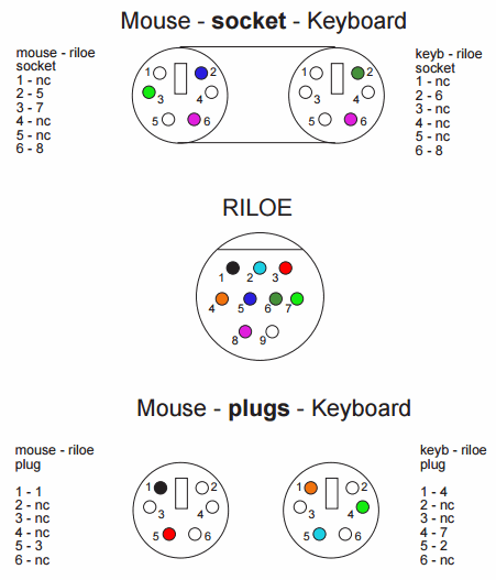
I went the extra mile and created a pinout (also available as PDF here). It’s not tested though.
riloe

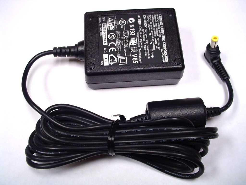
The power supply looks like this:

RiLOe power supply

10 volts, Plus inside, minus outside of the plug.

Geekdot page relaunch!

Woohoo! Geekdot.com got a complete overhaul.
About nearly everything has changed… besides the content of course.
The most obvious change is the complete responsive design. That means reading GeekDot on your smartphone or tablet should be much easier now.
Also every social bells’n’whistle is activated – so you can comment, quote, twitter and FB-like nearly everything… if you don’t have better things to do 😉

Over the coming weeks I will keep on smoothing the edges. Every feedback from you is very welcomed.

Manufacturing PCBs in China?

Ever thought about manufacturing PCBs in China?

If you google this, you most certainly end up with “your mileage my vary”. Indeed it does… and here are my 2 cents:

Because the grass might be greener on the other side of the river, I’ve tested and will keep on testing several PCB houses over the time. So I’ll update this Blog post every now and then… until now, I wrote about

ShenZhen2U

[Oct 2014]
For my AM-B404 TRAM I hadn’t had any other option than have them manufactured in China. 6 Layers and sub-20$ weren’t possible anywhere else. So I tried ShenZhen2U

Ordering

After sending in the Eagle-CAD files their support was great. Several Mails with their engineer (Hi Iver!)  flew back and forth, during which he created a multi-panel board out of my single board design and turned it into a Gerber file and let me having it for a final check before everything went into production.

Quality

Manufacturing and shipping was OKish (20 days in total). At first sight, everything looked great. Nice, professionally framed SMD stencil, PCBs etc were carefully bubble wrapped.
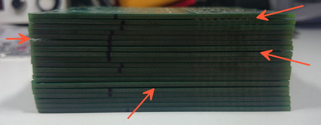
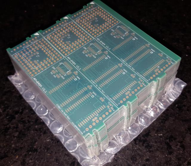
When squeezing the whole stack of PCB it felt a bit ‘bouncy’ – looking at it from the side, it became clear why:

ShenZhenBent

Some PCBs were bent. You can see the gaps between some of them.

Well, when the PCBs were from the 3-part panel separated it wasn’t that obvious anymore. So I started populating them.
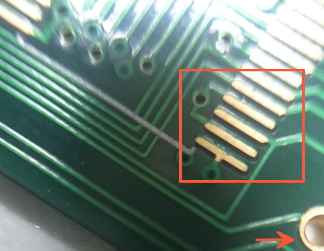
This brought me to the next issue. The silkscreen was quite a bit off on some of the PCBs. Luckily, all of them had enough solder pad left to be usable:

ShenZhenMask

In the end, 3 of the 60 boards were completely unusable. They had shorts within the internal layers which couldn’t be fixed even by cutting traces and re-wiring.
I guess all those glitches are the price you have to pay when going “cheapo”.

Update Nov 2015:
I ran a 2nd batch of the same boards from the same Gerber files and mentioned the non-working boards in the 1st order.
This time the quality was very good and they silently added 2 extra boards to my order. Thumbs up, ShenZen2U!

Update March 2017:
I asked for a quote for the same design, same number of boards but their price increased 30% within 15 months – so I had to find another manufacturer capable of doing 6 layers.

Dirt Cheap PCBs

For my QFP-to-BGA adapter – which just uses 2 layers – I tried Dirt Cheap PCBs. I really like the attitude of their site and for just 25 bucks for 10 PCBs it was worth a shot.

Ordering

It’s a no-brainer. Upload your eagleCAD/Gerber file and wait – after some minutes you can even look at a rendering of the top- and bottom layer of your boards. They explicitly state, that this function is beta and yes, 1 of the ~5 times I used their service, that rendering wasn’t totally correct – so don’t wet your pants if this happens. Use a real Gerber viewer instead. That said, you normally have 1-2 days to update your files if I might have found a mistake later.
About 20 days later I got my little brown envelope. Everything’s fine, I’m totally OK with it.
Before using their service, be sure to check their FAQ. You’ll find jewels like this:
The board house will add three tiny numbers to your board: batch ID, a customer number, and our PCB ID. This is so everyone knows which crappy PCBs to send you. Don’t like it? Tough. Buy an entire panel somewhere else.

Update: I also tried their 4 layer service (for which they use an external board house) and while the price is good, the results were so-so.
They did not place the solder-mask on the most fine-pitch part (QFP 100pin) which is a pain in the a** to reflow without getting shorts 🙁

Seeedstudio

A more posh version of manufacturing PCBs in China is Seeedstudio who asked me to check out their “Fusion” service. They even offered me a $30 coupon (thanks!), so why not give it a try?!

Before sending my Gerber files I had a couple of questions and their email service is very good an responsive.
As they offer hard-gold finishing, I thought it might be a good time to create an expansion card with its connectors being plated with hard-gold to make it more robust to plugging the card in and out a couple of 100 times… some mails flew back and forth but in the end they asked for the same price for having the connector-fingers done in hard-gold as having done the whole PCB done in this process (the rest was planned in HASL). That’s 30 vs 230 bucks! Erm, no thanks… not this time.

Ordering

So I ordered some standard 2-layer, HASL finished PCBs, no bells and whistles on Fri. Nov. 25th. Their order form is well designed and shouldn’t leave you with any questions – they even offer a Gerber viewer of your uploaded files, which I think is very cool!
(One hint: When entering your address, the form insists that you enter an EORI tax-number which private persons normally don’t have. A simple dash “-” does the trick, though).
They offer 3 ways of shipping, ~10€ for normal post (10+ days), DHL and FedEx (both 3+ days). I went for DHL – I’m pretty sure “normal post” wasn’t an option for my order when I had the choice. Maybe because of the weight…
Next day the boards went into production.  You’ll be updated about the proceedings by mail – pretty standard today – as well as in you accounts order history on their page.

On Nov. 29th I got an email confirmation, that my PCBs are finished and shipped… and on Dec. 3rd I got the boards in my mailbox. That was blazing fast indeed! 9 days from ordering to receiving

Quality

The cool thing is, that I’ve ordered the predecessor of this design at “Dirt Cheap PCB”, so I have a direct comparison.
Given the simplicity of the design, I haven’t found any glitches or mistakes… the two boards are nearly identical.
If you’re super picky about your design: like Dirt Cheap PCB, Seeed does print some internal ID on your silkscreen – and that’s not in their FAQ.

Conclusion

For a simple design (2-4 layers, no extras) Seeedstudio is comparable to other PCB houses – even a tiny bit more expensive.
Where they shine is when it comes down to support and all those extra features like penalization, V-grooves etc. which the other houses just can’t offer or leave you in the cold when it comes down to getting help.

PCBWIN

So after ShenZen2U became too expensive for my budget (They’re still cheaper than European services) I found PCBWIN being another Chinese manufacturer able to provide 6 Layers for a reasonable price.

Ordering

The order process was very convenient. After  requestin a quote online I’ve been contacted by my ‘personal sales assistant’ (Hi Betty!) straight away.
Their engineers checked my Gerber, clarified some measurements, v-groves etc. which I could explain by sending photographs and drawings. All in all, very a professional and reassuring process during which you also can contact your personal contact by Skype, e.g. if you’re really on a time-pressure.
I can’t give a usual delivery time for this order, as my fell into the  Quingming Festival season, so that added some extra days of delay – but they informed me about this, so all OK here! Including this delay, it took 10 days until shipping. After the usual 20 days wait and some more queuing at the customs office I got this:

Quality

The PCBs and a new stencil were well packed – and a quick visual check (ENIG, masks, printing) was quite satisfying. If there’s anything to critic, maybe the silkscreen printing was a bit  ‘thin’ – but that’s really a minor thing. The first PCB I’ve populated and tested worked fine – so I assume the other 29 will be fine, too 😉

After-sales are great, too. So your personal assistant will stay in touch and is honestly interested in how everything worked out etc.

Conclusion

So as with any other PCB service, it’s the people that make the difference. Yeah, the price is an important item on the list, but as the saying goes: If you buy too cheap, you’ll buy twice.
For me PCBWIN was a win. Thumbs up!

Do you have/had any good/bad experiences with Chinese PCB manufacturers? I’m happy to hear about it in the comments below!

QFP Adapter

Again, a man had to do, what a man has to do…
My good friend Udo gave me some Transputers in QFP package, most of them previously used and unsoldered from some PCB. Nobody knows, if they are still OK or already braindead – so I needed a QFP Adapter.

As fate goes, some fine day I stumbled across a nice 100pin QFP burn-in socket from Yamaichi on ePay. Yamaichi is “the other company” producing burn-in sockets besides 3M with their Textool brand range.
Normally those sockets are insanely expensive (100US$++) but this was a lucky buy – well for the “price” that it was an EOL model… for many years. This means no documentation available. But the very kind sales team of Yamaichi Germany (Vielen Dank Frau Howe!) was able to dig out a hand drawn blueprint of this very socket, model #IC51-1004-139.
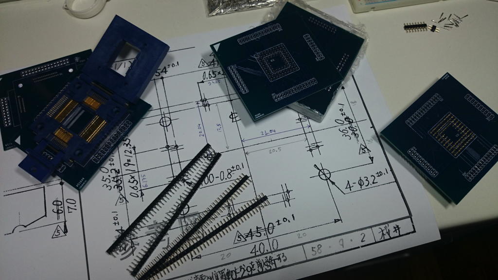
This valuable Information at hand I was able to create my own Eagle CAD device for this Socket – not an easy task as most measures were not directly given but had to be calculated using other documented distances. After some hours I ended up with two PCBs, one for the burn-in socket which again will be mounted onto a PGA-Pin adapter PCB.
When done it was time for another “first”: Try the DirtCheapPCBs service. 2 Layers, 10x10cm PCB, 10 pieces for just US$25 (incl. shipping) – almost cheaper than doing it yourself.
After two and a half weeks I had two stacks of 10 PCBs each. Anxiously I tried if the socket with its tiiiiiiny pins will fit…. and… it… did! Hooray!! I didn’t expected that but everything fit perfectly, even the silkscreen. Soldering the 0.025″ pitch was another story…

But see for your self. Upper left corner you see the burn-in socket already soldered. At the right edge, the lower PCB it waiting to get 84 Pins soldered for the PGA socket… and another 100 to connect to the upper PCB.

QFPAdaptor

Feel free to contact me, if it happen to be that you also found an IC51-1004-139 socket and need the Eagle lib or even the PCB for it… I have 9 of them left 😉

Handling TRAMS

The five TRAM handling commandments

  1. Ground yourself – touch something which is grounded, eg. PC case, radiator etc…
  2. Handle TRAMs with care! The pins are thin and break off fast.
  3. Check the pins for straightness before inserting
  4. Never assume the end with the Transputer is pin-1. Look for the marked corner indicating pin-1.
  5. Pull TRAMs slow and evenly. Pins might get bent/broken (see #2).

In detail

TRAM pins are thinner than normal PCB-Pins e.g. those you may know from Arduino shields. They are, well, quite fragile. That’s a problem (by design) with all TRAMs.
So be very careful when handling TRAMs, i.e. removing/plugging them from/into your TRAM carrier e.g. a IMS B008.

And you can’t repeat this enough: Ground yourself! Electrostatic discharge will kill your TRAM and the Transputer on it – as well as any other electronic device.

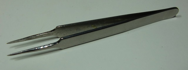
How do I do it? My main and single tool for handling TRAMs is this pair of straight tweezers:

Pliers

This works quite well for carefully removing TRAMs from its socket by putting it between TRAM and socket like this and gently lever the TRAM – not too much! Else you will bent the pins on the other side – repeat on the other side. Done.

The Transputer

If you got you TRAM without a Transputer plugged in, you might figure that it’s quite difficult to plug in the CPU. My suggestion:

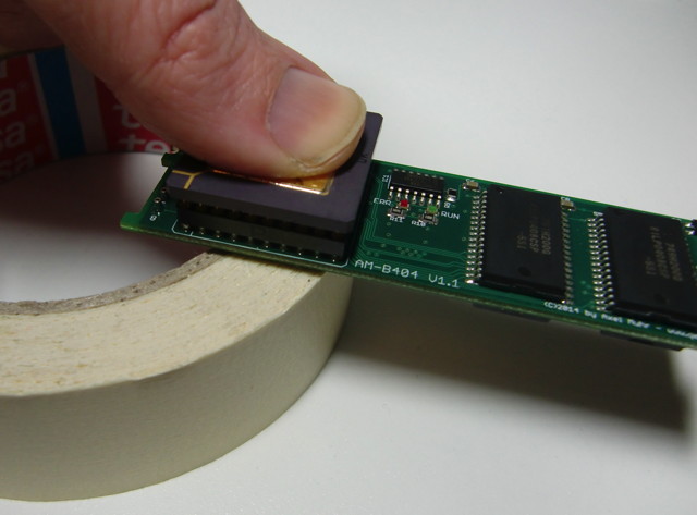
Put the back of the TRAM (the socket pins only – refrain from putting any force onto the TRAM pins) on a medium-soft item, e.g. a block of wood or like I usually do it, onto the rim of a sticky-tape roll, and press the CPU using even force into the socket with your thumb.
Double check that all CPU pins are straight and are sliding into the socket holes without force and fiddling. Also, mind the CPU orientation!
Again, never push the Transputer into its socket without support underneath the socket, your TRAM will bend and traces might break rendering it useless. At minimum the TRAM-pins will be damaged.

CPUpress

It’s worse when you’re in need of removing the CPU. Sometimes the ceramic packaging is extremely brittle and the CPU pins do sit very tight in the socket.

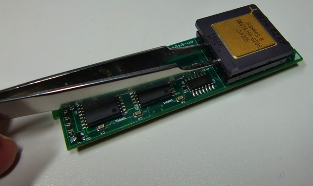
Again, use a straight tweezer, gently pushed between the socket and the CPU and carefully lever the CPU for a millimeter max.

CPUlever2

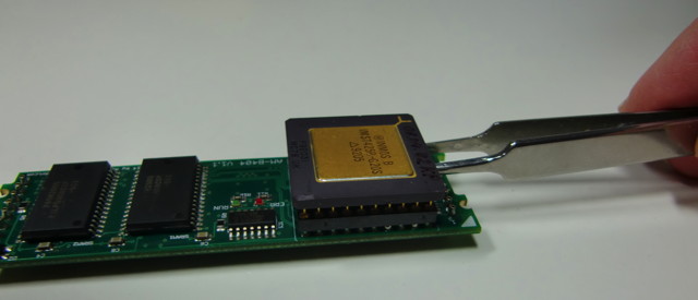
Repeat on all four sides of the CPU…

CPUlever1

Take your time. No reason to hurry.