All posts by Axel

http://www.geekdot.com/about-me/

T2i2c got real!

The “Transputer to i2c project” aka T2I2C finally developed into a real circuit board! Check it out here… and that just the start:

Not only is the T2i2c probably the first new TRAM since 1997 but it’s the kickoff for all my planned “30 Years Transputers” jubilee events. Stay tuned!

If you only have a Hammer…

…every problem looks like a nail.

Why the rant? Well, a new mobile phone was due and I was bored by my iPhone. So as a matter of fact I could choose between the plague or cholera… ok, after Apple owned my mobile data the last 5 years it’s just fair to let Google have its share, too. Gasp! How could i!? 🙂

It wouldn’t be me if I would not mention ‘the good old days’. So let me divagate a bit:

In the long gone past, I was a avid defender of [enter the current favorite system here] versus the rest of the world, e.g. “C64 vs. ATARI XL vs. Amstrad/Schneider vs. Sinclair vs. Apple II” or “ATARI ST vs. AMIGA vs. PC (286 that was) vs. QL vs. Mac”. We spent hours to defend “our” system against other crap-computers and the same was true later on, when it came down to the OS arm-wrestling: Windoze vs. MacOS (we’re talking 7 here) vs. RISCOS vs. OS/2 vs. Linux (v0.94ish)… not mentioning 68k vs. x86 vs. ARM vs. Transputer.
Over the time I got more relaxed and maybe wiser -did I say that?!- and chose the mantra used in the headline: “If you only have a Hammer, every problem looks like a nail”.
When you’re young and financially limited you have to chose clever, or not, and then you’re doomed to stick with it until you can afford something better/newer… and because you’re stuck, you have to defend your decision with a knife between your teeth. Later you might get the idea, that it’s quicker to open & edit that damn document with Windows than converting it 10 times wasting an hour… and it’s just clever to use 3 lines of perl/bash/python instead of Batch-file kludges or HyperCard (remember that?).

That said: I officially quit OS/System/CPU wars. I pick what fits best for the job – that does not turn me into a fanboy of that choice.
Why? If you take a closer look at my examples given in the beginning of this rant, you might get the point straight away: I was just mentioning some of the available systems at those days. So the choice was big and with its possible combinations it was a huge offering to chose from.
Today, it’s very simple, mostly A, B or C: Windows, Linux/*BSD  or MacOS. iOS; Android or “the remaining 5% of the market”; x86, ARM or, mhh, MIPS perhaps. Boring. Very Boring. Yawn.

How about you? Are you still fanboy’ing about today-tech?

Newtech thoughts wk37

It’s not the case that I do not have a look at what’s going on in ‘Today-Tech’, as a matter of fact I have to know what’s going on in order to get the bread on the table. That said, and you might have guessed it already, normally I’m not really impressed by the latest ‘old wine in new bottles’.
But every now and then, there’s something which actually makes me raising an eyebrow (yeah, call me Spock ;-)) and if it’s really cool or totally crappy, I’m happy to share it here with you. So let’s see what I came along:

This is crazy shit. I really love it. Watch the video – it makes you go “oh my god!”.

On the other hand, that…

iphone-5s

…is just boring. Besides the small changes, can someone please explain the idea of 64bit in a mobile phone? More than 4GB RAM? Hardcore math?

This one might be the first (recent) Smartwatch I might spend a second look at. Even it’s Android… but it might actually be available in stores (gasp!)

sony_sw2

Coming back to the “old wine in new wineskins”, we all know that Smartwatches are nothing new, do we? Let me name a few: Seiko UC-2000 (1984), the EPSON RC-20 (archived URL) (1985, Z80 CPU, still have one NOS) and the famous Ruputer later called OnHand PC (1998). I was really close to buy a Ruputer back in 1998 but after building a 1:1 model out of paper (sic!) I had to admit that my wrist is just not big enough… and it still is 🙁
Side-note: I had a rather long’ish look at the WIMM watch… and when I was thiiiiis close to order a Dev-Kit they were swallowed by that one big company that rules them all – no, it’s not Microsoft anymore 😉

The answer to the why-question

If you have read some of the articles on this page, you might already got bored about the constant mention of “real men hardware” or the notion of some boring technical stuff being “nice”, “sexy” or just “beautiful”… well, I admit you have to be a bit geeky to fully understand that right from the spot but this rant tries to explain this a bit more in detail – especially because I hear the “why?” question a lot.

“Once upon a time…”

If you talk to geek-veterans (born before 1975) it often may happen to you that they start sentences with “Back then…” or “In those days, when everything was much nicer,…“. This is because the computing world wasn’t anything but settled. Many things were in flux, you had to fiddle a lot to make a computer to do more than just print some text on a screen or printer – and there were certainly many roads which led to Rome.
It was not god-given that you could have graphics (i.e. not just text) maybe in color -gasp!- or sound/music beyond a pathetic beep… and even if you had a graphic output, monochrome 280×192 pixels were called high res!

It’s becoming obvious that this page centers around technologies from 1988-1993’ish. So it’s not Commodore 64 or Apple II stuff which you would probably call “stone age hardware”, but still those Workstations, Cray-in-a-Chip or Super-Highresdevices are pathetic compared to todays PDAs or even mobile phones, not to mention current (personal) computers – the simplest things we got used to today are nearly impossible:
Animated 3D Graphics? With some extra CPU(s) I could rotate a wire-frame cube for you.
Playing MP3 files? Well, if you have a fast enough DSP that might work…
Surfing the web? Surfing what?
Burning a 4GB ISO image? Does it fit on my super-macho 5.25″ full-hight 200MB hard-drive?
Use that funky API for doing XYZ? Sure, if you code the driver first…

So what the fuzz?!

Deo in machina

It’s the esprit, the spirit, the ingeniousness which makes those old dogs so fascinating. You had to go the extra mile to reach nearly anything which is daily routine today. And while ASICs weren’t that fast as they’re today, most things were handled by additional general purpose CPU(s) or special coprocessors/chipsets like those used in Commodores AMIGA machines.

For example, the combo of a high-end TIGA graphic card and an additional, full-length accelerator containing a 33MHz MIPS R3000 CPU was able to display 10.000 triangles/s of 100 pixels, flat-shaded.
In 1994 a PlayStation (the first one, using the same MIPS CPU) did 360.000 flat-shaded polygons/s – so you get an idea, how “fast” a supposedly fast graphics card was back then… well, don’t forget that everybody else was still happy with 320×200 256-colors 2D graphics (that’s standard mode 0x13 VGA).

There you have it: Why? Because it’s still fascinating what engineers were doing to reach their goals. Squeezing the last drip out of everything.
Then, if you’re able to revive all this today and have it successfully running, it’s like an old steam train making its first “breath” after years of hiatus: Impressive.

Sparky 2

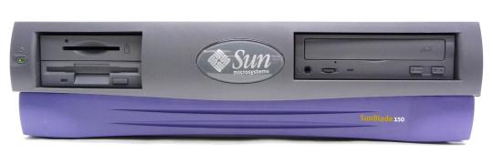
Meet Sparky 2, my main Solaris box. Yeah, Sparky2 isn’t exactly a roman or greek mythical figure, even the ‘sun theme’ would give you hundreds of possible god, godess and daemon names but there’s a reason.
Sparky2s main reason d’etre is Helios core development. As far as my research in the sources went, Perihelions main dev-box was called Sparky – so to honor their work I continued to use this name.

Hardware

Sparky2 is actually the 2nd incarnation of my Solaris dev-box. “Sparky-1.5” was/is a lovely SparcStation 20, dual SuperSparc-60 CPU, 384MB RAM and even a on-board CG14-Framebuffer.
But that beast is just loud. Loud fans and a loud SCA-SCSI drive. As with most of my vintage computers, I was thinking and planning to replace everything to make it nearly noiseless but while the power-supply fan was doable, the hard-drive replacement would result in unjustifiable costs… and still it wouldn’t been any faster then.

So here it is, the ultimate “Solaris-Box-which-can-run-even-in-your-bedroom™”: A Blade 150.

case

Yes, you’re right, pretty recent stuff (2000-2006) for Axels ususal crap equipment, and in a Sun hardware evangelists view, it’s not even worth being called “a SUN”, but I needed it to run silent, and because the Blade 100/150 series is mainly build from standard PC parts, it’s perfect for noisless tuning.
It comes in a small ATX-desktop case, uses IDE drives, a standard ATX power-supply, standard PC133 ECC DIMMs (cheap these days!) and the 650MHz UltraSparc IIi CPU is fast enough to compile any vintage project in matters of minutes and not hours.

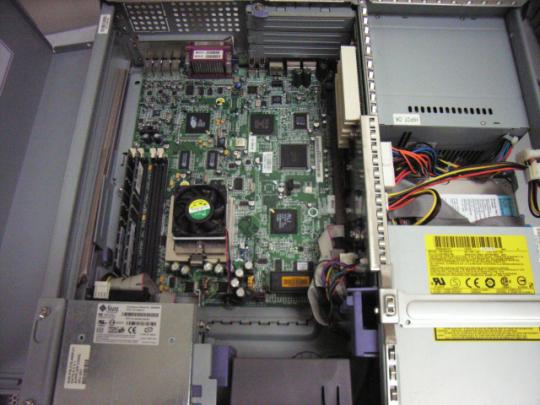
internals

So out went the power-supply fan as well as the case-fan in the front and both were replaced by my noise-killer-of-choice: BeQuiet! fans.
The supplied Seagate IDE drive is already very silent, so I didn’t replaced that by some IDEtoSDCARD adapter or even a SSD (no, it wouldn’t be faster, the interface is ATA66).
As for the CPU-fan I was told that some (more silent) NVIDIA fans perfectly fit – need to try that later found a better solution, see post below.

Software

Depending what you’re planning to do with it, a blade supports IIRC Solaris from version 7 up to 10. In my humble opinion Solaris 8 is the best OS to fiddle around with vintage sources: “Modern” enough and still featuring SunOS 4.1.x compatibility through the ‘SunOS Binary Compatibility Package” (called SUNWbcp).

While not necessarily needed for vintage coding, I still think it’s a must-have: pkgutil from the OpenCSW project – especially since Sunfreeware is unixpackages.com now, which isn’t free anymore.
Contrary to this, pkgutil is the ultimate & free package-manager and just works as you might got used on other platforms (yum, ipkg and such). It’s much of a relief when you finally got basics like bash, less and another-editor-than-vi etc. Here’s how to get started.

Most important of all, you’ll obviously will need gcc. I had good results with GCC 2.95 which is not available on OpenCSW, but if you know how to Google, you’ll find it for sure 😉

A new start

Ok, the page seems to look like it did before. Right. But everything has changed:

  • First of all, after 15 years the sites hosting was moved, the OS upgraded and everything just smells sooooo up-to-date
  • The CMS was brought to the newes release making it much quicker
  • A Blog was added. Yeah, lame today-tech, but if I might feel the urge to post something, there’s a place for it now… and you can comment on my stuff. Hey! If that’s not tempting?!

But there’s more to come. I was working on quite a big retro-project the last months which might actually interest more people than the usual 10 suspects. Stay tuned – it won’t be another 2 months, promised!

Well, ok…

Ok, it had to happen one day. Everybody and his/her dog has a blog today, and sometimes I have to admit, I’d like to to give my 2 cents about things just happened/happened in the good old days or something I just discovered for myself which does not exactly fit into the normal GeekDot webpage. So here it is: The GeekDot blog.

Not sure if there will be many posts, but good to know I could, if I need to…

While you were obviously digging deeper, you might have seen that there’s a commenting facillity down there. Because I’m too lazy to create a commenting feature myself or fiddle around with 10+ plugins of my (ex) CMS I simply use(ed) DISQUS giving a plenthora of features as a plus. If you don’t like that or know better solutions, just leave a comment below 😉

T2I2C – The nitty-gritty details

Ok, so you saw the thing in action and now you want to know more – maybe even build an interface yourself because you’re one of the other ~15 guys on this planet still fooling around with Transputers 😉

Good news! This time I created circuit diagram so you can actually make you own T2I2C – and that’s not enough: I’ve already laid out a TRAM-1 size circuit board using SMD parts of the C011 and 8574 making space for piggy-backing an Arduino Uno on top of that board.

But let’s start with the other details I mentioned the chapter before. I’m totally aware that there are many, many things to improve and optimize – and then there are probably even more I’m not aware of.
Here’s the how and why I did things they way I did:

Oneway

For this first version of T2I2C I’m using an C011 in ‘mode 1’ – that means it is offering actually two 8-bit buses, one for receiving (input, I0-7)) and one for transmitting (output, Q0-7). Because it’s quick and easy I don’t use the I-bus and therefor grounded it.
This means there’s no way for the Arduino to talk to the Transputer side of things. But using an extra bus for input would mean using a second 8574 and obviously using another 4 wires on the ATMega.

The elegant solution to this is using the C011 in ‘mode-2’ – it then behaves like a C012 which means it provides a single butbidirectional 8-bit bus. So why didn’t I used mode-2 in the first-place?
Well, while mode-1 just requires 2 lines for data-control, mode-2 needs 4 lines and some more coding in the ATMega ‘firmware’ e.g. handling the 2 registers provided by a C012 – So yes, I was just lazy and wanted results quick. The next release will certainly use mode-2.

Handshaking

So what is that data-control you’ve mentioned? Using 2 converters (C011/8574) in a row there’s obviously a need for all parties to know when data has arrived and needs to be processed.
The C011 as well as the 8574 provide a pin which flags a “hey, we have something here!” signal (QValid in the C011, /INT in the 8574) . But in contrast to the 8574 the C011 also needs an “Ok, got the data, feel free to fetch the next one” – which is called “QAck”. So the ATMega controls the data-flow talking to the C011 and completely ignores the 8574 which makes it somewhat transparent.
The comms protocol of the C011 can be found in its data-sheet here. It’s all about reading, holding and releasing QValid/QAck in the right timing.

First I was using an external interrupt line on the ATMega connected to QValid because it’s so obvious. But somehow the results were flaky – sometimes the ATMega seemed do choke on some bytes which simply didn’t make it through(*). After some cursing and hair-ripping I decided to switch back to polling – again because I was lazy and wanted to get results 😉
Up to now polling QValid just works great, probably because the ATMega is pretty fast and I2C is pretty slow.
(*) Yes, of course I’ve read all the docs about interrupt-programing and its caveats (short routines, volatile vars etc…) didn’t help.

Achtung! Kommando!

So what is actually going on in the ATMega running “Se Fiiiirmwarrre”? As mentioned in the previous chapter, I decided not to send a complete ‘bitmap’ of 128bytes each time an update occurs. Instead I created a simple command protocol, (currently) consisting of 3 bytes:

  • 1st byte: If < 255 it’s the number of the Transputer data. If 255 (0xFF) command flag set.
  • 2nd byte: If 1st-byte < 255, it’s the CPU-load in percent, else it’s acommand.
  • 3rd byte: If 1st-byte < 255, it’s the Memory-load in percent.

This means a single Transputer information update only takes 3 bytes. A command like “clear the display” is just a single byte.

Of course there are downsides. Updating a complete display of 128 Transputer-loads means sending 384 bytes instead of 128 bytes needed for a bitmap (512 pixels, 2 bits each = 1024bits = 128bytes) – But OTOH you could enhance the firmware for just that case: One command initiates a bitmap-transfer and then you send the 128bytes of data. Mind the could, i.e. this command doesn’t exist yet.

What comes on top of the handling/processing is the calculations needed to be done by the ATMega. There’s a command telling the ATMega how to setup the panel according to columns. If there are less than 33 Transputers to be displayed, each Transputers gets its own line of 16 LEDs. To display 64 Transputers, it will be divided into 2 columns with 8 LED each. 96 Transputers have to get along with 5 LEDs and 128 can only use 4.
No matter how many Transputers have to be displayed, poor ATMega first has to calculate the percentage value into 16, 8, 5 or 4 LEDs, then decide into which column this value goes and finally handle the displaying itself – worst case a 128 times. All this could be circumvent with a bitmap-transfer, offloading all those calculations to the sender (a Transputer in this case). But I’m not sure if this is much cleverer…

The Arduino source (.ino file) is available here. I suggest you have the Arduino Software installed.
There’s still debugging code in the source, putting out info on Arduinos USB/Serial port.

These are the commands currently implemented (in decimal):

001 – 015 : Set display brightness (0..15)
031 – 034 : Set the columns to be displayed (1..4)
099 : Clear the panel display
100 : Toggle CPU-load-only vs. CPU & RAM load mode

Hardware

Like you’ve seen in the video, there’s no real circuit board existing yet there wasn’t a real circuit board around back then. But I’ve created a board layout for a TRAM-1 containing an SMD C011 and 8574 which provides the space needed for a socket to plug in anArduino Nano (the small version of an Arduino Duemilanove) – Version 3.x to be precise. You have to use a V3.0 or higher if you want to use my ‘firmware’ out of the box! This is because the analogue pins (A0-A7) have been rotated in V3.x and up – if you plan to use an earlier version of the Nano, you have to adjust the i2c-pin definition in the firmware source.
Anyhow – Using an Arduino Nano is much more flexible -and cost saving- than putting everything incl. the ATMega on the board itself.
The socket is laid out to be “double-row”, so you can still plug wires right next the Arduinos pins – well, actually this is mandatory at least for connecting to the LED panel.

Currently (v1.0) these pins are used/defined by the firmware on Arduino:

  • Portd: 7, 6, 5 and 4 for connecting the LED panel
  • Analogue input pins 4 & 5 (SDA/SCL) for the I2C bus
  • Portd: Pin 2 connects to QVAL, Pin 3 to QACK on the C011
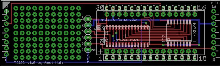
board

I tried to layout the board in such way that it could also be used as stand-alone, i.e. without being seated into a TRAM slot. Then you would have to provide the Links, 5V, GND, a 5MHz clock and Reset yourself via the alternative connector in the middle of the board, called “ALT_C” . There is still room left which I’ve used for a little breadboard section.

This design is to be considered v1.0 – still things to improve, especially a way to choose the link to be used if the board is actually plugged into a TRAM socket. v1.0 routes LinkIn/Out to the ALT_C socket which needs to be air-wired to the TRAM-pins… not nice but does its job.

If interested, you can download the Eagle CAD files here.

After nearly a year I was able to get a hand full of boards created and populated one using my brand new reflow oven (Reworked pizza oven) and voilá, here’s the T2i2c in flesh, naked:
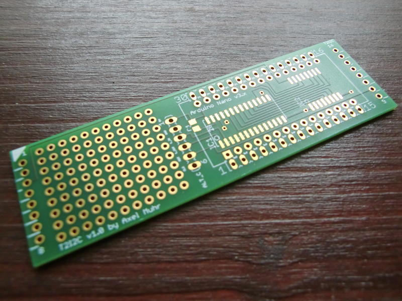
T2i2c_naked

…a bit more dressed (all parts place)…
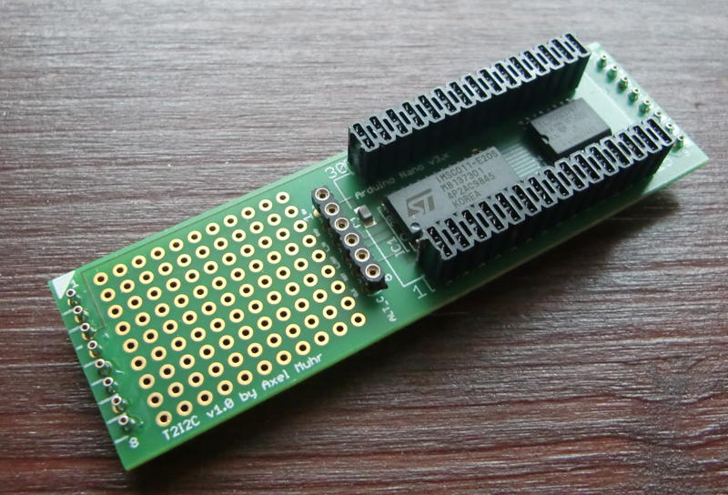
T2i2c_dressed

…and finally fully dressed (Nano plugged in):
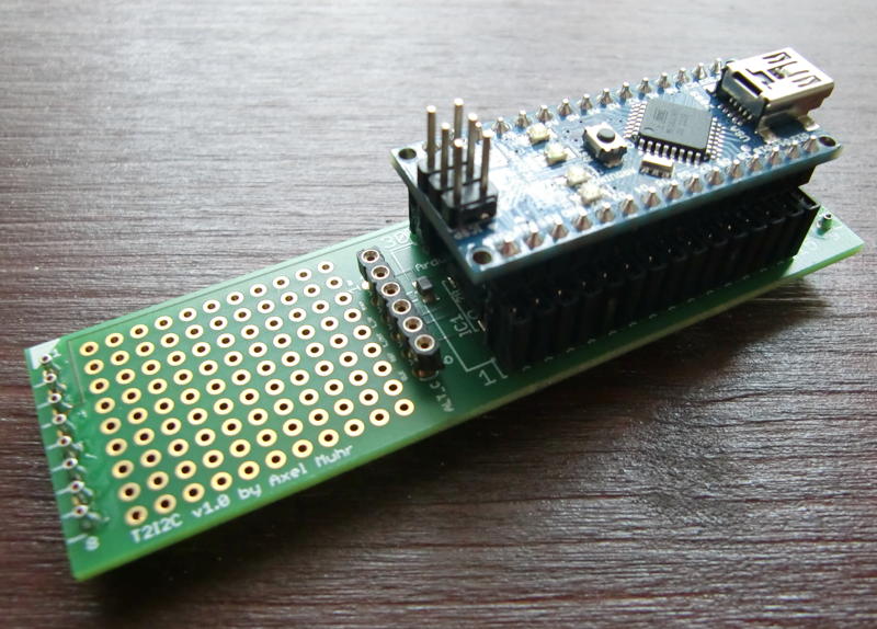
T2i2c_fullyDressed

So the final question was: Will it actually work? Yes it did! I plugged it into slot 2 of my beloved BOZO, connected the LED panel and adjusted my Helios test-sources a bit, and tadaa:
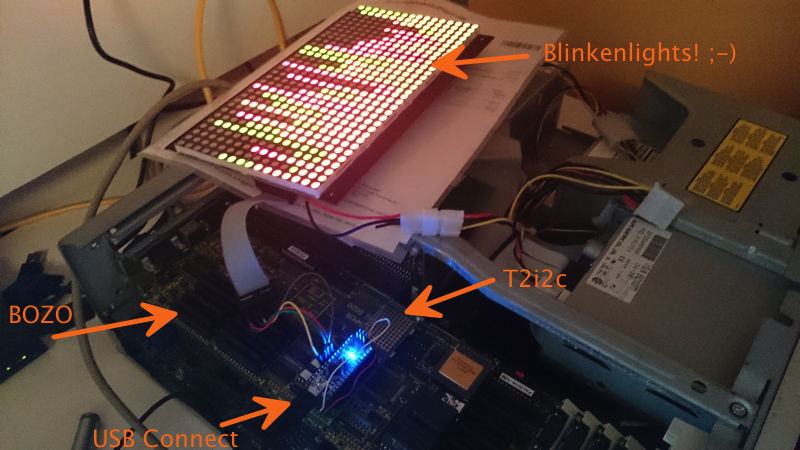
T2i2c

The cool side-effect of this project is, that you can keep the USB cable connected to your host, while the T2i2c is actually running in a system, giving a perfect  OS-link-sniffer for what’s going on in a Transputer setup.

Also, I reworked my Helios tools for checking the T2I2C functionality. Everthing is now in one single tool, i.e. test-pattern, clearing the panel or manually sending a command. Here’s the source as well as the executableread the source header before using! You can crash your Helios system – you’ve been warned!

Outlook

I won’t say the sky is the limit, but if the T2I2C-TRAM will be full-duplex in the next release (ie. C011 in Mode-2) driving an LED panel would be just one of many other uses this TRAM could fulfill.
Think of all the million things people did with their ATMega/Arduinos: LCD-Displays, SD-Card Interface, Ethernet and then some more. Ok, the speed of I2C will limit that somewhat (I already have made prerequisites in my ‘firmware’ to put I2C into 400kHz/kbps “fast mode”) but still a nice interface for connecting today-tech to your yester-tech.


The T2i2c

Boy, my acronyms are really getting Star Wars’ish now… After the T2C64 and the T2A2, T2I2C sounds like a new protocol-robot but stands for “Transputer to I2C (Bus)”.
The I2C bus is a comparably slow serial bus – even to the Transputers 1990 standards – but in contrast to the Transputer OS-link interface I2C is still alive and kicking… even more since those simple-to-tinker-with controllers like ATMEGA or PIC made there way beneath your soldering gun.

As you might have guessed by now, the I2C bus wasn’t my primary intention to do this interface.
Since I started fooling around with Transputers I was thinking of an LED “CPU load display” like the one the lovely BeBox had… just bigger, a real manly Blinkenlights 😀 It should be at least capable of showing the load of up to 32 Transputers…
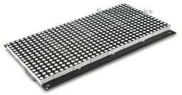
So I stumbled across a very nice bi-color 32×16 LED panel (Sure Electronics DP14211 – it seems in 2022 that company was either sold or folded), which is quite easily controllable through one small ATMEGA controller.

LEDPanel

By incident, a friend of mine gave me an surplus Arduino as a present and the decision was made. I’ve build & programmed ATMEL devices before, but Arduino plus breadboard can’t be beaten if you need to get something done quick.

Blinkenlights

It’s quite straightforward to connect the panel (can one say “display”? Nahh.) to the Arduino. To make things even more ‘bus-y’ the ATMEGA talks over just 4 wires to the panel over SPI bus – yet another serial bus, but luckily we don’t have to care about that fact as there’s a library handling this.
So after some days of coding, the “panel firmware” was done. The Arduino is happily talking to the panel over the SPI bus and listening on his I2C bus (another 4 wires) for commands and sends the calculated output to the panel.

Commands? Well, I was thinking about how to handle the data in an efficient manner. The most simple way would have been to have the Transputer sending the complete 32×16 ‘bitmap’. For a bi-color panel (2 bits per pixel) that would have been 1024bits/128bytes each time/interval.
To be more flexible I came up with a 3-byte command structure – for details see the next post.

Old guy speaking new language

So how to connect a Transputer to an IC2 ‘device’? We need two things for that:

  1. The good ol’ C012/11 Link Adapter – turning Transputer links into an 8-bit parallel bus
  2. An 8bit bus-to-I2C converter

We saw the C012/11 in some of my projects already, so piece of cake here. The 2nd converter needed some research and was easily found: A Philips/NXP PCF8574(A). So without control-lines the setup is quite simple:

Transputer → C012 → PCF8574 → Arduino → LED panel

After some hassle with handshaking (see next post “nitty gritty details”) I was able to send bytes to the display using MS-DOS’debug.exe to write bytes to the standard Transputer link IO ports (0x150++, you should know that by now ;-)) using a nice tool called ‘iskip.btl‘ from the INMOS ANSI-C Toolset (also available in my Transputer Toolkit). It simply shortcuts one Transputer link to another, e.g. Link 0 to Link 2. This relieves you from removing your Transputer and put jumper-wires into its socket… very nice and clean solution.

Doing it the right way

Well, while talking to devices through debug is definitely geeky, it’s not what I wanted as a result.
Having more than one Transputer running, watching its CPU and probably RAM load leads to the inevitable target of Helios. At least that’s the No.1 reason I created this interface… but with the command structure of the ‘firmware’ you’re obviously not bound to that OS, e.g. OCCAM programs could control the panel, too.

So the biggest development part was creating a clean way of taking to the panel while running Helios. For debugging and testing I wrote a simple command-line tool which opens a link on the Transputer you have the shell running on, then it sends what ever byte you added as parameter. Fine.
Next was version 2 of that tool, sending 32 fictional CPU-load values (0-100%), version 3 did the same adding RAM-load values.
Then it was time to do it the right way – so I dived into the sources of ‘network‘. network is the Helios tool for examining the Transputer (not IP!) network(s), so it shows the actual load in nice bar charts etc. – pretty much like top does on todays Unices.
While the sources of Helios are available, they seemed to be accumulated from different sources, dumped into an ISO image without caring for symbolic links etc. – in a sentence: They’re a mess.
After some days of try’n’error I was able to compile the sources of network. This made network2 (working name) possible which includes the new parameter ‘led’ followed by the number of the Transputer link to be used, eg. ‘network2 led 2‘ results in displaying the current CPU/RAM load of all Transputers in the network on the panels.
CPU-load is displayed by red LEDs, RAM-load uses green LEDs, overlapping is shown orange. As long as there are up to 32 Transputers each line represents one Transputer (using 16 LEDs). If there are >32 and <65 each line will be split into 2 columns (8 LEDs for each Transputer). This goes on for >64 and <97 (3 columns) and finally 4 columns for up to 128 Transputers – this isn’t very ‘readable’ anymore given there are only 4 LEDs left for one Transputer, but hey! It’s Blinkenlights, who cares!?

So without much further ado, here’s the prototype-beast in action:

For more details, thoughts, outlook and code see the next post.