The IMSB430 is a rare, yet interesting and important TRAM. It’s been meant for hardware developers to easily build and test prototypes before producing actual PCBs.
Interesting enough, next to no documentation besides a sales brochure has survived. So it’s time for reverse engineering… again. This is also an official call for help – If you by any chance know more about this TRAM, please contact me!
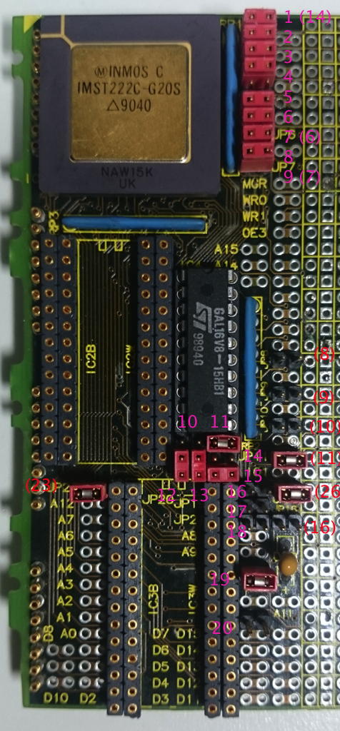
Here’s the left side of this size-4 TRAM. The other half is just the prototyping grid with lots of through holes which we can omit here.
I tried to number all jumpers on the board starting at the top – numbers in brackets are the jumper-numbers actually printed on the boards silk-screen. That numbering is a bit confusing and seems not to follow any logic.
IC connections
Buzzing through all lines from/to the GAL leads to this table so far:
1 ProcClkOut
20 VCC
2 A13
19 Mem0 (IC2B „/CE“ + JP26)
3 A14
18 Mem1 (IC3B „/CE“ + „J20“)
4 A15
17 1Wait (IO 2-above JP8)
5 notMemCE
16 2Wait (IO above JP8)
6 WaitSEL0 (JP8)
15 3Wait (IO below JP8)
7 WaitSEL1 (JP9)
14 SelWait (MemWait+ IO below JP9)
8 Map0 (JP10)
13 BLK0 (IO below JP10)
9 Map1 (JP11)
12 BLK1 („IO1“ below JP11)
10 GND
11 (I/OE) GNDed
Each SRAM socket is actually a “double row”.
If you seat your SRAMs aligned to the right, they will be accessed word-wide (16bit, D0-A15). When aligned to the left, they are accessed byte-wide (8bit, D0-A7). That’s why the silkscreen print says “IC2B/IC2W“…
Jumpers
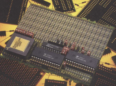
This is the official press photo. It seems to show the default jumper settings (using the full 64KB SRAM, word-access):
Some jumpers are already identified (“JP” precedes the official jumpers, “J” is my numbering):
Jumper
description
1
MemWait (FIT=GalPin14, else ????)
2
DisIntRam (FIT=use internal RAM)
3
ProcSpeedSel0 (FIT=HoldToGnd T222)
4
MemReq (FIT=no request)
5
EventReq (FIT=no request)
6
MemBacc (FIT=word access)
7 (JP6)
ProcSpeedSel2 (FIT=HoldToGnd T222)
8
BootFromRom (FIT=BootFromLink)
9 (JP7)
ProcSpeedSel1 (FIT=HoldToGnd T222)
JP8
Set MemWaitstate Bit0
JP9
Set MemWaitstate Bit1
JP26
Connects /OE with /CE of IC2 (upper SRAM)
J20
Connects /OE with /CE of IC3 (lower SRAM)
The external RAM access wait-states can be set with JP8/9:
As soon you’re talking about Transputers with people which weren’t there back in 1985 you’ll be asked this very soon: “How fast are these Transputer thingies”? Then there’s a stakkato of “MIPS? Whetstones? Dhrystones?” etc…
As always with benchmarks, the only valid answer is “it depends”. Concerning Transputers that’s even more true.
First, I suggest you read this Lies, Damn lies and benchmarks document from INMOS itself. It pretty much describes the dilemma and all the smoke and mirrors around that matter.
Benchmarks? It depends.
So you’ve read the above INMOS document? As you might saw, it’s full of OCCAM code. That’s the #1 prerequisite to get fast, competitive code (as long you’re not into Transputer assembler). From there it gets worse if you use a C compiler or even FORTRAN…
My little benchmark
Because it scales so well, works with integer as well as floating point CPUs and also runs on the x86 host while using at least the same graphic output routines, my personal benchmark is CSAs Mandelbrot tool (DOS only).
My slightly modified version is part of my Transputer Toolkit, which is downloadable here. You will need that version because I extended the code of this Mandelzoom with a high precision timer (TCHRT, shareware, can’t remove the splashscreen, sorry) when run with the “-a” parameter. You’ll need my provided default “MAN.DAT” file, which contains 2 coordinates to calculate (1st & 2nd run) to get comparable numbers.
So to bench your Transputer system start it with:
man -v -a
which runs it in VGA mode (640x480x16c), loads the coordinates from “MAN.DAT” and when done presents you with a summary screen like this:
To run it on your hosts x86 CPU, call it with “man -t -v -a”
The Results
Here are my results of the different Mandelzoon runs I made in the past. The blue background marks the host machine results, yellow are the integer timings and green is where the mucho macho things are happening.. well, sort of 😉
There are two columns for the results, the HD timer and the hand-timed runtimes. This is because these are from days before I enhanced the Mandelzoom.
This table will continously updated of course. e.g. the last row is pretty new – what might that system be? 😯
The sources are available in my github repository – so we can collaborate on enhancing and optimizing it.
HD in-programm Timer (s)
Hand-Timed
System
1st
2nd
1st run
2nd run
Comment
i386DX/33 (0kb L2)
1800
0
1:30:00
(canceled)
0
Canceled 1st run after a quarter of Mandelbrot was done…
i386DX/33 (0kb L2) + 387
588
3316
0:09:48
0:55:16
Am386/40 (0kb L2) + 387
490
2980
0:08:10
0:49:40
21% faster clock but only 10.5% better result
i386DX/33 (128k L2) + 387
274
1547
0:04:34
0:25:47
Am386DX/40 (128k L2) + 387
228
1292
0:03:48
0:21:32
i486DX/33 (8k L1, 0k L2)
01:06.24
368.56
Pretty close to a single T800-20
i486DX2/66 (8k L1, 128k L2)
00:33.72
185.51
Very close to 2x T800-20
Pentium 133 (256kb L2)
00:09.09
00:55.01
About 8x T800-20
Pentium 200 MMX
00:07.13
00:38.06
About 9x T800-20
AMD K6-3+/266
00:06.00
00:32.00
Downclocked, 64k L1, 256kb L2, 1M L3
Core i3-2120 3.3GHz
00:01.66
00:02.13
VirtualBox,1 CPU
1x T425-20
0:00:25
0:02:28
There’s something wrong here – needs re-run
2x T425-20
00:51.55
04:56.60
3x T425-20
00:34.42
03:17.81
4x T425-20
00:25.86
02:28.56
5x T425-20
00:20.74
01:58.96
6x T425-20
00:17.37
01:39.19
9x T425-20
11
62
0:00:11
0:01:02
13x T425-20
8
42
0:00:08
0:00:42
21x T425-20
5
27
0:00:05
0:00:27
25x T425-20
4
23
0:00:04
0:00:23
65xT425 (48x25Mhz, 16x20MHz)
00:02.323
00:08.163
Actually it was 64xT800 and one T425 forcing the calculation to integer
1x T800-20
01:09.13
06:27.18
1x T800-25
0:00:55
0:05:09
25% higher clockrate should result in 17.5% speedup. Incl comm-overhead that pretty much fits
1x T800-30
00:00.46
00:04.30
2x T800-20
00:35.65
03:13.79
3x T800-20
00:23.16
02:09.32
4x T800-20
00:17.43
01:37.04
5x T800-20
00:14.04
01:17.74
6x T800-20
00:11.82
01:04.83
5x T800-25
11
62
0:00:11
0:01:02
9x T800-20
8
40
0:00:08
0:00:40
13x T800-20
5
30
0:00:05
0:00:30
17x T800-25
00:03.8
00:18.59
“1st run” shows that the slow ISA interface is really getting a bottleneck
This is the first post on GeekDot about a single IC. While I did a lot of writing about ICs, mainly CPUs and FPUs, back in the BBS days (German) I stopped doing so after that and concentrated on collecting them during the following years – a true love never dies 😉
The Weitek Abacus FPUs were always special, exotic and unaffordable for the most of us. Today they additionally got a touch of a mythic being, especially as 386/486 boards featuring the special WEITEK socket are dying out fast. Not mentioning the Abacus FPU itself.
Recently I had a mail conversation about the Abacuses and because they’re are memory mapped, I thought they might actually fit quite good into the range of my other accelerator post as the DSM860 or all those Transputer cards.
I wasn’t planning to go into all the details about the Abacus models 3167 and 4167 and went looking for a handy Wikipedia link.
To my surprise that article is pretty general and just briefly touches all product ever made by WEITEK.
So, the best source of technical information about these FPUs is the highly recommendable posting “copro16a.txt“, written by Norbert Juffa in 1994.
I’d call it the most comprehensive write-up about FPUs until that date. Because you’ll never know what happens to external links, here’s the (shortened) part about the Weitek chips:
The architecture of the Weitek chips differs significantly from the 80x87.
Strictly speaking, the Weitek Abacus 3167 and 4167 are not coprocessors in that they do not transparently extend the CPU architecture; rather, they could be described as highly-specialized, memory-mapped IO devices. But as the term "coprocessor" has been traditionally used for these chips, they will
be referred to as such here.

The Weitek coprocessors have a RISC-like architecture which has been tuned for maximum performance. Only a small instruction set has been implemented in the chip, but each instruction executes at a very high speed (usually only a few clock cycles each). [...]
In contrast to the 80x87 family, the Weitek Abacus does not support a double extended format, has no built-in transcendental functions, and does not support denormals. The resources required to implement such features have instead been devoted to implement the basic arithmetic operations as fast as possible.

While the 80x87 coprocessors perform all internal calculations in double extended precision and therefore have about the same performance for single and double-precision calculations, the Weitek features explicit single and double-precision operations. For applications that require only single-precision operations, the Weitek can therefore provide very high performance, as single-precision operations are about twice as fast as their double-precision counterparts. Also, since the Weitek Abacus has more registers than the 80x87 coprocessors (31 versus 8), values can be kept in registers more often and have to be loaded from memory less frequently. This also leads to performance gains.
[...]

To the main CPU, the Weitek Abacus appears as a 64 KB block of memory starting at physical address 0C0000000h. Each address in this range corresponds to a coprocessor instruction. Accessing a specified memory location within this block with a MOV instruction causes the corresponding Weitek instruction to be executed. (The instructions have been cleverly assigned to memory locations in such a way that loads to consecutive coprocessor registers can make use of the 386/486 MOVS string instruction.)
This memory-mapped interface is much faster than the IO-oriented protocol that is used to couple the CPU to an 80287 or 80387 coprocessor. The Weitek's memory block can actually be assigned to any logical address using the MMU (memory management unit) in the 386/486's protected and virtual modes. This also means that the Weitek Abacus *cannot* be used in the real mode of those processors, since their physical starting address (0C0000000h) is not within the 1 MByte address range and the MMU is inoperable in real mode. However, DOS programs can make use of the Weitek by using a DOS extender or a memory manager (such as QEMM or EMM386) that runs in protected/virtual mode itself and can therefore map the Weitek's memory block to any desired location in the 1 MByte address range.

Typically the FS segment register is then set up to point to the Weitek's memory block. On the 80486, this technique has severe drawbacks, as using the FS: prefix takes an additional clock cycle, thereby nearly halving the performance of the 4167. Most DOS-based compilers exhibit this problem, so the only way around it is to code in assembly language.
Ok, so we have a good idea how the Abacuses work and how they can be used. … but what’s the story behind the company?
When dramatically loosing ground to the 486DX2 Weitek moved away from the x86 platform and concentrated on SPARC CPU and FPUs as well as MIPS FPUs. That worked quite well for some time and in the 90s they finally moved into the frame buffer and graphics accelerator business. Their POWER P9000/P9100 models were quite successful but lost when players like S3 and ATI started to flex muscles.
Specs
So from our (PC-compatible) perspective there are two models of interest: The 3167 and the 4167. Basically they only differ in the bus protocol to either the Intel 386 or 486.
If you need more detailed data, I make the original specs available here for the 3167 and 4167 as PDF.
Both Abacuses clocked up to 33MHz. Especially the 4167-33MHz is very hard to find these days. That said, it might be possible to overclock a 25MHz version to 33MHz providing sufficient cooling. I found this press snippet where WEITEK proactively promoted overclocking a 33MHz to 50MHz by using a peltier element made by ICECAP – so when overclocking that by 51%, the 32% from 25 to 33MHz should be an issue:
WEITEK and ICECAP announce 33MHz version of Abacus 4167
Ram Ganapathi Mar 30 1992, 02:57 pm
WEITEK and ICECAP announce 33MHz version of Abacus 4167
Weitek Corporation and ICECAP Technologies announced today that users of 50MHz Intel 80486-based personal computers can realize a 50% performance increase for numeric-intensive applications by combining the 33 MHz version of Weitek’s Abacus 4167 math coprocessor with the ICECAP thermal management device. Superior system performance is achieved without degrading system reliability.
Using it
Applications that took advantage of the Weitek Abacus were scarce. AutoShade, Autodesk Renderman, 3-D Studio were the most prominent to use a Weitek coprocessor.
If you happen to own one, you might actually use or at least test it… so here’s the official test-suite from Weitek. It contains these tools
DOS TSR to update the BIOS for Abacus support (if missing)
A test tool wich checks for an Abacus presence using INT 11h BIOS calls.
A diagnose tool
2 demos: A side-by-side Mandelbrot benchmark (yay!) and rendering a phong shaded beach ball
Abacus macros for using it natively in your cool assembly code
When I find the time to pull out my Weitek-PC, I’ll post pictures of the demos… feel free to comment if you feel I’ve been missing out something.
Working with vintage computers has many aspects and one of them, nearly throughout every component, is noise.
Hard-drives whirr, floppy-disks rattle, the CRT emits a high-pitch whistle and on top of it all at least one fan is blowing like a jet-engine. Time for a fan replacement!
Luckily since these days, much quieter fans have been developed during the last 30 years – so let’s just swap the fan and… ahhh, silence. I did that with my Sun Blade 150 and it worked great!
…well, it’s actually not that simple all the time.
Blown by the wind
System cooling was handled a bit different back in the 80’s and 90’s. Practically there were just 3 levels of cooling:
Insane – Either huuuuuge Fans (>8″) or some mad-scientist liquid-cooling was used. I won’t touch these in this post…
The “no fan” class were all so-called home-computers and the lower-end models of the early 16-bit machines like the ATARI ST, Commodore Amiga 500 or the first Apple Macintoshes (Steve Jobs was fanatic about convection cooling).
The most prominent “single fan” family members were office PCs up to the 486-class as well as any desktop/deskside 68k Apple Macintosh. All these had one fan sitting in their power-supply, blowing the warm air out to the back of the case.
Please mind the warm air. We’re not talking hot streams of death-rays here. While CPUs weren’t a big heat-source issue (until the advent of the i486/50) passive heatsinks were sufficient to cool them by the air-flow/draft through the case created by the PSU.
For such Personal Computer systems it can be perfectly fine to replace some old, noisy fans with recent high-tech whirls. Especially if the PSU was also replaced by something more modern (like I did with my Quadra 950) producing less heat than the original one.
This is a totally different story when it comes down to workstations.
An en-vogue (UNIX) workstation back in the days was mostly designed using a relatively small pizza-box sized case, nicely snuggling underneath a monstrous 21″ CRT. To name just a few there were
SUN SparcStation 1 to 20
SGI Indy
Digital VAX/DECstation
Many HP PA-RISC 7xx
These boxes were cramped (hard-drives, expansion cards, lots of RAM) and their high-end processors ran much hotter than those x86 and 68k in personal computers.
Surprisingly none of them had a dedicated CPU fan mounted – instead they all relied on the power of the fan installed in the PSU.
Under pressure
Searching the web, you will find many texts recommending to put a quieter PC into your workstation. Vintage-me says: Don’t!
In case of workstations (pun intended!) a new indicator is needed in the game of fan replacement.
While the ‘PC world’ just looks at the CFM value (cubic feet per minute, i.e. airflow) as a performance indicator, workstation owners need to check the static pressure delivered by a fan. This is measured in mm/H20 (millimeter of water) and means how strong is a fan pulling air over obstacles and/or through venting slits etc. – think vacuum cleaner.
In consequence, two fans having about the same CFM value might be completely different when it comes down to static pressure. This is a nice table I found on the web comparing some high-performance fans with standard PC ones and the Papst 8412N is a good example of what I just wrote: The much liked NF-A8 has just 25% less CFM but only half the mm/H20:
Fan
Airflow [CFM]
Static pressure [mmH2O]
RPM
Noise [dB]
Panaflo FBA08A12U1A
46.9
4.8
3450
38.2
EBM Papst 8412N
40.6
4
3100
32.0
Noctua NF-A8 FLX
30
1.96
2000
16.1
Noctua NF-R8
31
1.4
1800
17.1
Arctic F8
31
1
2000
20
That power naturally comes at a price: More revs and much more noise… which is inevitable at the given mm/H20 power.
What’s cooking?
So what happens if I chose the wrong fan?
If a low-pressure fan is placed in an airflow path with lots of obstacles, the fan’s airflow will reduce and it will cool only the nearby components, but won’t have enough juice to suck heat from parts further away.
This means it will only cool (parts of) the power supply and the rest of the workstation will be more-or-less cooled by convection and the internal temperature will accumulate. Running such a machine for a longer duration will lead to ‘effects’. From errors to crashes, even smoke and finally destruction.
“C’mon, that’s folklore, Axel!” – Not a bit my friend.
I just had this experience when I thought that my MIPS RS2030 workstation could do just fine with a somewhat more silent, recent fan. The original one is/was a Delta AFB0812HH – a hellish loud fan. But even a Noctua NF-A8 with a mm/H2O of nearly 2 made the small MIPS workstation unstable. First the PSU housing got really warm in the middle (switching regulators are screwed onto it there) and after 30 minutes of torture (compiling code) I got more and more SCSI I/O errors until the system completely froze.
Changing the fan back to the noisy one everything ran rock-solid. Quod erat demonstrandum!
So what should I do?
There’s no general advise to follow. If you want to keep your original PSU it might be possible to use a more silent fan for just the PSU and add one or more fans caring for the case ventilation.
Your milage may vary and multiple modern fans -which also need to be mounted somehow- might add up producing the same amount of noise like the single original did.
The cleanest solution is replacing the original PSU innards by more modern & smaller parts which then draw less power and therefore dissipate less heat, requiring less cooling.
This is especially advisable if you have the feeling that the original PSU gives fist signs of ageing (smell, heat, buzzing). Better safe than sorry!
[UPDATE 2025 – got a CacheDoubler! 😍 See further down for added details]
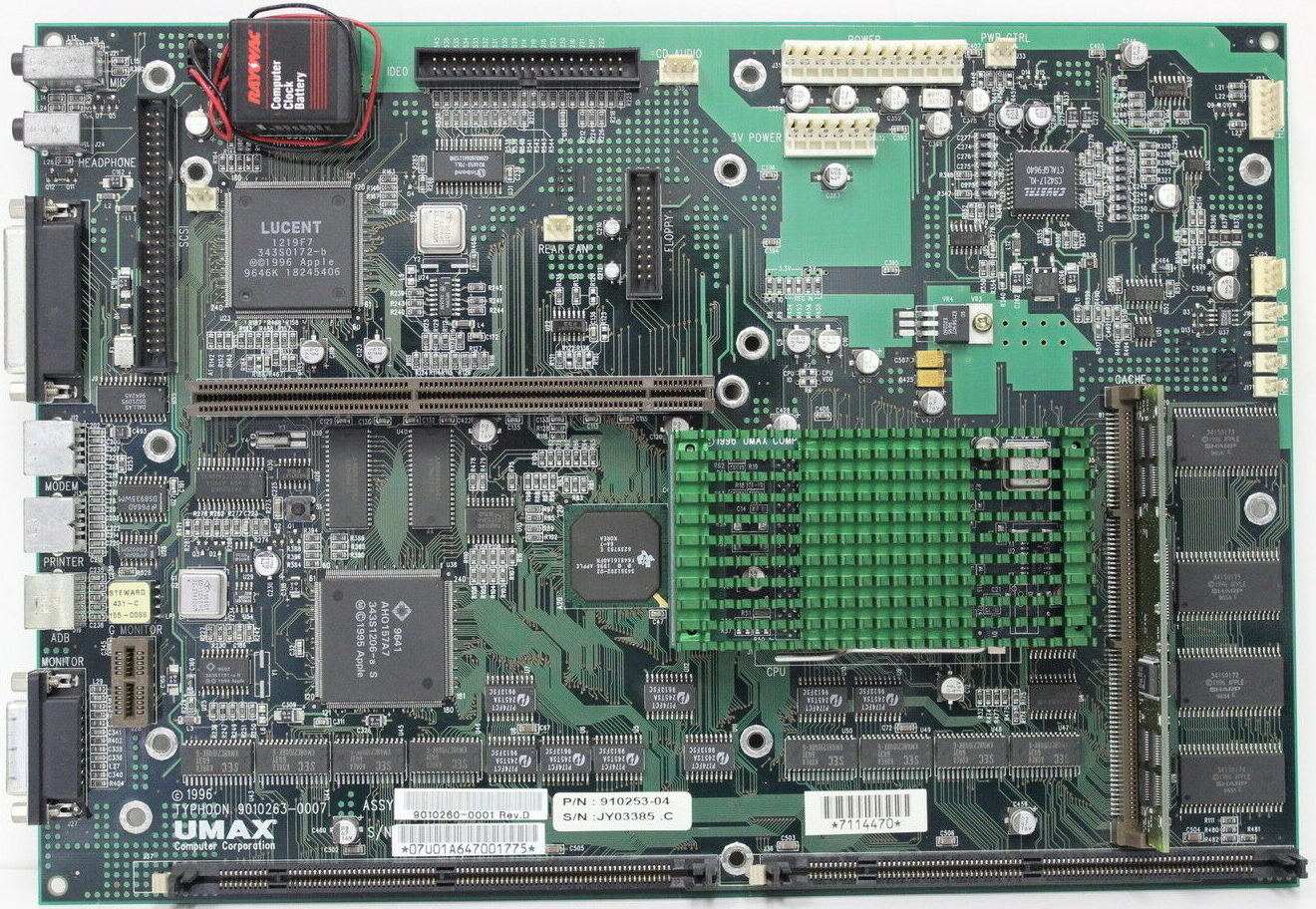
Apple Performa and PowerMac models 5400/6400 used a mainboard code-named “Alchemy“. The same board, sometimes with some changes, was used in different Mac clones like the UMAX Apus 2000 & 3000 series (SuperMac C500 & C600 in the US) and PowerComputing PowerBase.
One fine day I got an UMAX Apus 2k, which uses a derivate of this board, re-cristened to “Typhoon” which you can see here in it’s full beauty:
Processor
Apple: PowerPC 603e
Power Computing: PowerPC 603e, 750
Umax: PowerPC 603e, 750
Only Power Computing and Umax can be upgraded
Systembus
40 MHz
fixed
L2-Cache
Slot for 256k or 512k L2-Cache
RAM
5V DIMM 168 Pin 60 ns (EDO)
Apple: 2 DIMM-Slots, 8MB on-board (136MB max.)
Power Computing: 3 DIMM-Slots (160MB max, Bank 1 only 32MB, Bank 2&3 64MB)
Umax: 2 DIMM-Slots, 16MB on-board (144MB max.)
To the limit!
So being the way I am… I had to optimize it. Jus can’t help it 😉
Here are the steps I’ve taken – in the order of making sense the most and being less difficult:
RAM
Simple rule: The more, the better. This will get you the maximum performance – not in speed, but you can run memory-hungry applications without swapping (virtual memory) which is a major PITA and drags down everything.
That said, finding the correct RAM is also a pain because this board uses now very obsolete 5V buffered 168-pin DIMMs. 5 Volt is already hard to find – but the buffered version is even worse.
You can check that by looking at the coding keys (“groves”) at the DIMMs bottom:
The UMAX/SuperMac board can handle two 64MB DIMMs… if you can find & afford them.
L2 Cache
A “Level 2” cache is a must-have on all PPC machines. AFAIK UMAX/SuperMac did not sell their clones without one – Apple certainly did.
If your machine doesn’t have one, get one ASAP!
If you can get a bigger one than the one you have, do so!
None to 256K – increases CPU performance about 30 %
The overall responsiveness is dramatically increased
256K to 512K – adds about 20% performance.
512K to 1MB – need this SIMM! Mail me 😉
Umax offered an optional CacheDoubler PCB plugging between the socket and the CPU. It features an 1MB L2-Cache and upped the bus-clock to 80 MHz. AFAIK it came as standard in the UMAX C500x/C600x models.
Of course these are unicorns now and rare as chicken teeth.
NB: There are some caveats about the L2 cache discussed further down…
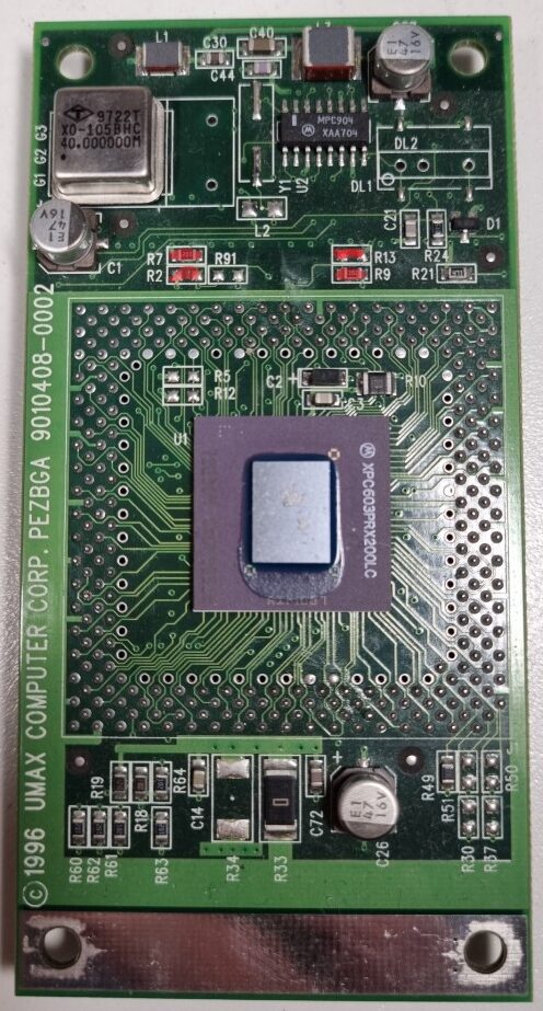
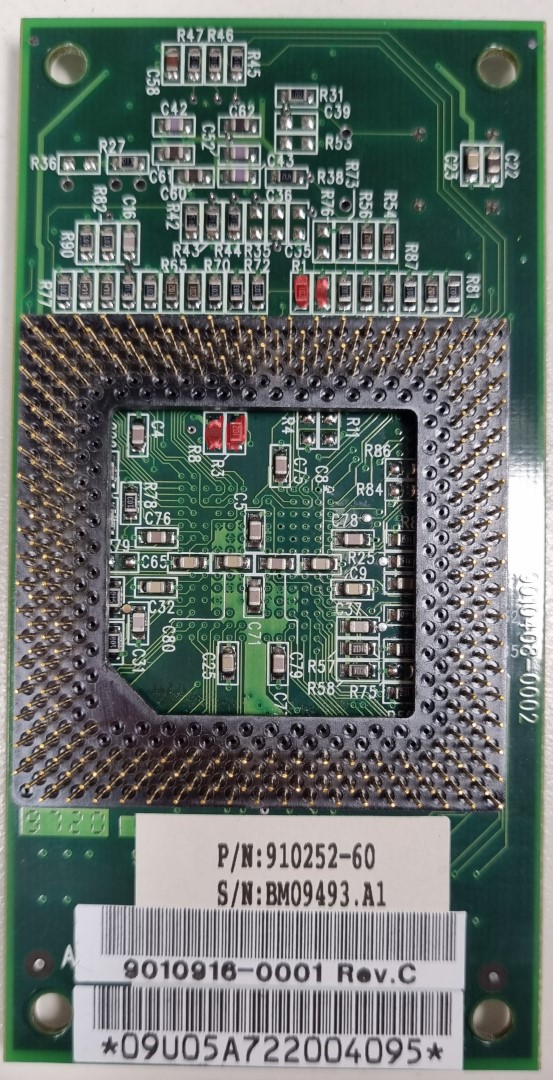
Faster CPU
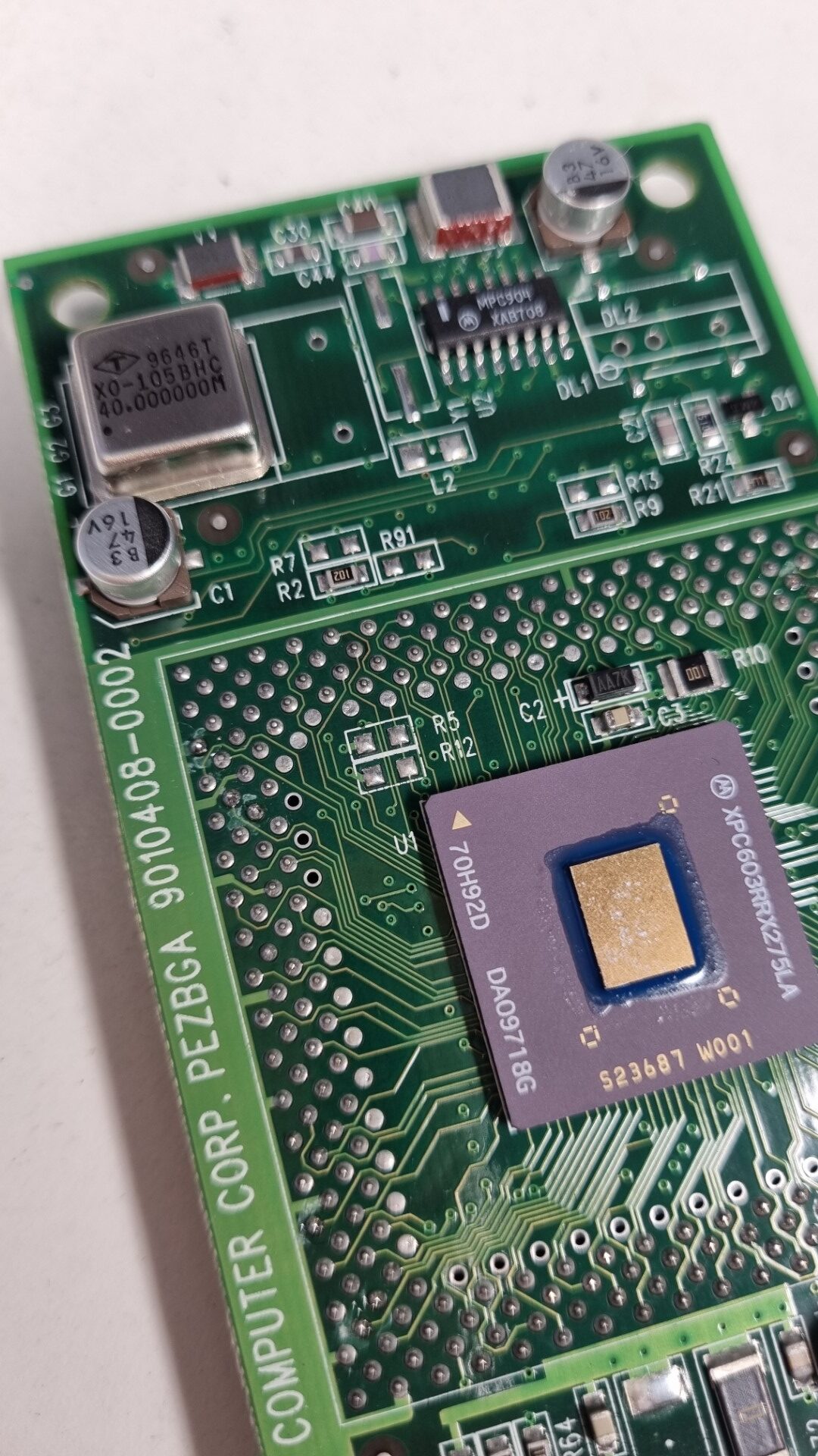
Yes, this board has a ZIF socket like the Pentiums did back then. And as such, you might be able to find a faster one. But unlike the Intel CPUs, these come on a small board covered by a big, green heat-sink.
Underneath is the CPU (in BGA package) a bit of logic, caps, lots of resistors and an oscillator.
So even if you were unable to find a faster CPU you can still ‘motivate’ yours – read: Overclocking!
As usual with overclocking, every CPU has its limits. The experiences with the 603e(v) used by UMAX are:
160Mhz to max. 225
200Mhz to max. 240
240Mhz to max. 270
How’s that done? Quite simple (if you’re ok with soldering 0603 SMD parts) by relocating some of 8 resistors which are on the top and bottom of the CPU card… marked red on the pictures below:
Use this table to change the CPU multiplier relative to the standard 40MHz bus-clock. There are also settings for 80-140MHz, but this is about overclocking so these make no sense whatsoever, right?
CPU Speed
160MHz
180MHz
200MHz
220MHz
240MHz
Busclock x
Multiplier
40 x 4
40 x 4.5
40 x 5
40 x 5.5
40 x 6
R1 [1.0k]
✔
❌
✔
✔
✔
R2 [1.0k]
❌
✔
❌
❌
✔
R3 [1.0k]
✔
✔
✔
❌
❌
R9 [1.0k]
❌
✔
✔
✔
✔
R6 [1.0k]
❌
✔
❌
❌
❌
R7 [1.0k]
✔
❌
✔
✔
❌
R8 [1.0k]
❌
❌
❌
✔
✔
R13[1.0k]
✔
❌
❌
❌
❌
Resistor color:Green = Bottom, Red= TOP
✔ = set, ❌ = not set
If the multiplier is not enough, you can also increase the bus-clock, too.
That way you can go up to a theoretical maximum of 300MHz 🔥
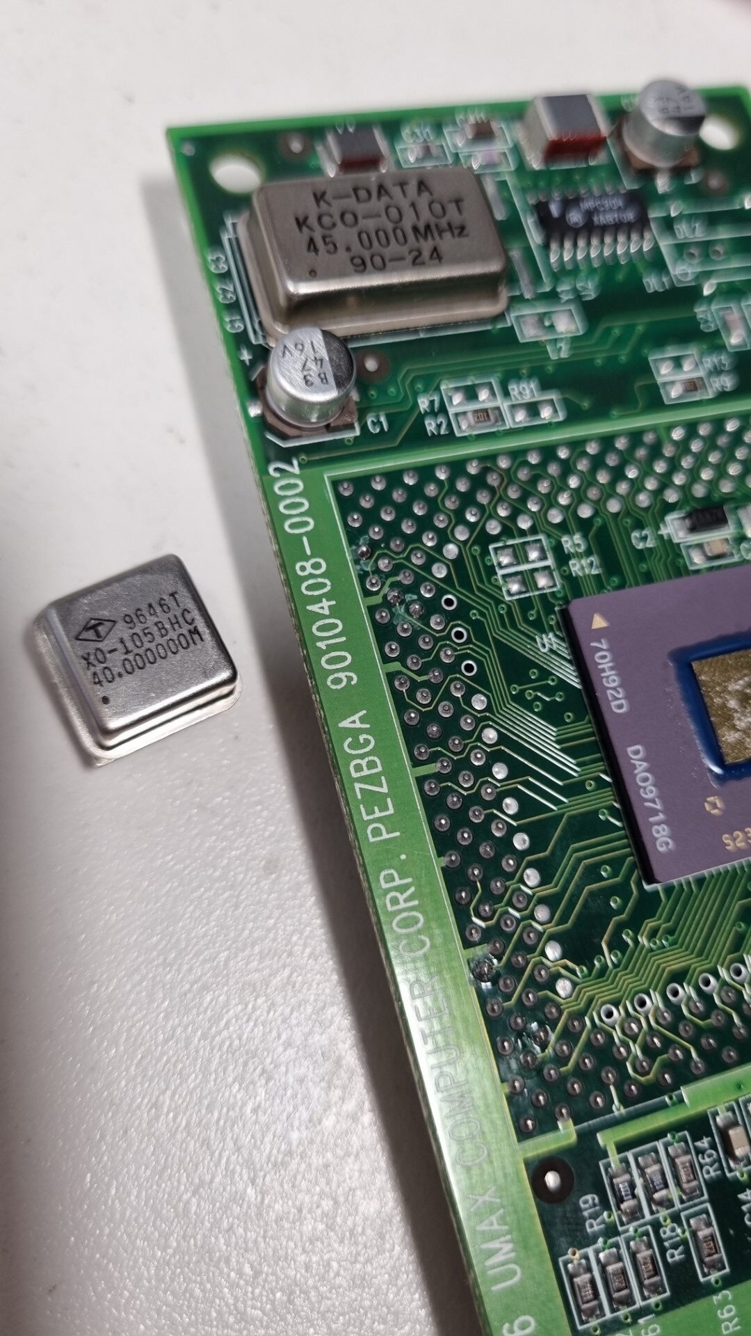
Oszillator
40.0MHz
45.0MHz
48.0MHz
50.0MHz
x4.0
160MHz
180MHz
192MHz
200MHz
x4.5
180MHz
202.5MHz
216MHz
225MHz
x5.0
200MHz
225MHz
240MHz
250MHz
x5.5
220MHz
247.5MHz
264MHz
275MHz
x6.0
240MHz
270MHz
288MHz
300MHz
As with the resistors, you’ll need some (de)soldering skills… but it’s a simple procedure: Old oscillator out, new one in. They were even kind enough to plan for a bigger oscillator case.
Before…
…and after.
For maximum bus-performance don’t use odd divisors like “x4.5”
☝ If you plan to overclock your bus to 50MHz or more you have to get a faster L2 cache…
Most 256K cache SIMMs seem to have an IDT7MP6071 controller using an IDT71216 TAG-RRAM which has a match-time of 12 ns (You can derive that from the marking “S12PF”” on the chip). That`s far too slow for 50MHz bus-clock. If you would be able to change the TAG-RAM to a 8 ns Part, it would probably work.
Bigger cache SIMMs seem to feature faster TAG RAMs. Here’s a nice thread on 68kmla.org on those SIMMs.
Finally, here’s a comment from an Motorola engineer referring to the Tanzania board (but same issue) I found in a corner of the web:
“One final problem is the main memory (DRAM) timing. If the firmware still thinks the bus clock is 40 MHz (25 ns), it won’t program enough access time (measured in clocks) at 50 MHz (20 ns). There are resistors to tell the firmware what the bus speed is, so that it can program the correct number of clocks into the PSX/PSX+ to get the required 60 ns access time. For the StarMax, this means removing R29 and installing it in the R28 location for 50 MHz operation.”
I have no clue (yet) if and where those resistors are on a Typhoon board.
Update 2025
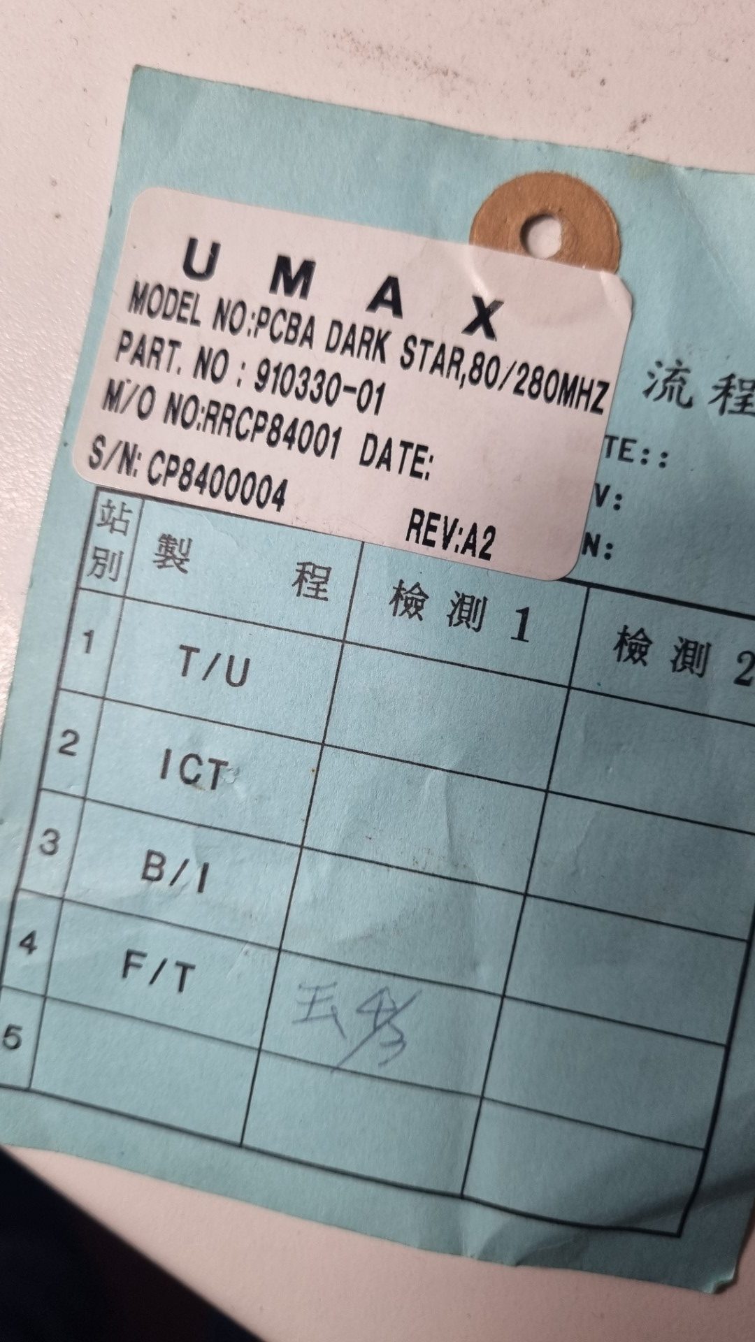
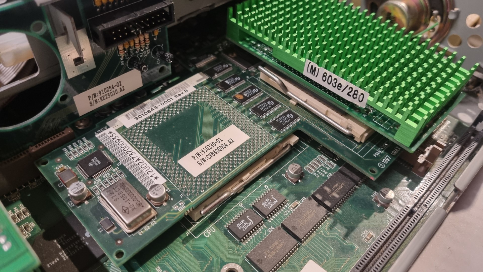
While I was asleep, my brother in arms Bolle wasn’t, so he saved the CacheDoubler which was on eBay for me! 😍
So after some days, look what the cat brought in:
a “Dark Star” Rev A2, aka the super-rare CacheDoubler… and in it went. Ahh, what a nice view!
Crossing fingers, power on, aaaaand:
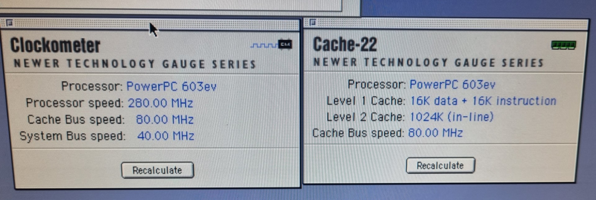
Woo-Hoo! Full steam ahead ahead🚀!
Now the CPU is clocked at 280MHz as it was meant to be… interesting enough, my bus overclocking on the CPU module is completely ignored. So it seems that the 80MHz crystal on the CacheDoubler is overruling it – multiplying it by 3.5 to get to the 280MHz CPU clock.
There would be room for experiments e.g. setting the multiplier to 4 or up the bus to 85MHz, but a can hold myself back, given the rarity of this board 😎.
And if this would be enough of luck, I found a pair of 64MB 5 Volt EDO DIMMs nearly the same day Bolles package arrived.
So this little UMAX x500 / APUS 2000 is now filled up to the brim.
Conclusion
So, what have I done in total?
I added as much RAM I was able to find (16MB on-board, one 16MB and one 32MB DIMM two 64MB DIMMs) to get a total of 64MB 144MB which is just OKish frickin’ awesome for a 603 PPC Mac
I wasn’t able to (yet) find any bigger or faster L2 cache than the 256KB I already had installed. So that one stayed as-is.
One megabyte of 80MHz inline L2 cache, baby! All my sub-G4 PowerMacs hate this litte UMAX for that 😉
I replaced my stock 200MHz 603e CPU with a module containing a 275MHz 603ev (Even the label says 280). It has its multiplier set to 6 already… so running on a 40MHz bus is runs at just 240MHz.
My wild guess is that it was meant for the CacheDoubler mentioned above and switched to a multiplier of 3.5… [you guessed right, Axel]
So I upped the bus-clock oscillator to 45MHz resulting in a 270MHz clock – 5Mhz below the CPUs spec but the bus is not stressed too much… the system runs stable and I measured a comfortable 45°C/113°F on the heat-sink.
This mod will be ignored by the CacheDoubler. So even the modded CPU module now runs at 280MHz.
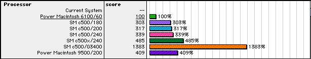
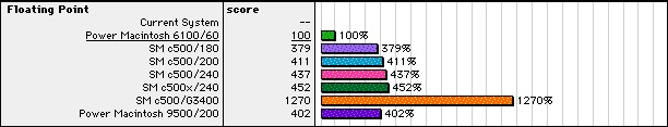
Here’s a Speedometer 4.02 comparison of before and after:
This shows that every CPU benchmark ran more or less those 35% faster, which are the difference of 200 vs 270MHz – even the Disk and Grafics performance increased between 7% and 10% which is also due to the increased bus-speed.
My system sorts itself 29% above the 240MHz machine concerning CPU performance… but FPU is less?!? No idea why that is.
Disk is probably a faster model than mine (WD Caviar 21600).
with CacheDoubler these numbers went up even more:
506 CPU (+37%) 474 FPU (+11%) 331 Disk (+12%)
Pretty nice for an 603e, huh? Yeah, that’s still way behind the crescendo G3/400 L2 accelerator… but therefore it’s all Supermac original 😉
What else
Well, 2 PCI slots… one for a standard 100Mbps NIC and the other one got a VillageTronic Picasso 520 which fits nicely in a System 8.5 Mac.
I tried a PCI USB card… that lead to constant boot-crashes. I should have google’d that first, else I would have known that “Although CacheDoubler does great things for performance, field reports indicate you cannot use a USB PCI card with CacheDoubler installed.” 🙄
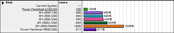
All my benchmarks were made with the original 1.6GB Western Digital IDE harddrive… which started to knock after a lot of read/write and installation experiments. So I tried other solutions:
BlueSCSI – works fine but is quite slow (124% in MacBench 4.0)
IBM DDRS 34560 – 4GB SCSI harddrive, pretty noisy but at least 279%… still slower than the IDE
Found a super silent 40GB IDE drive (Maxtor “DiamondMax Plus 8”) in my “Garbage Pile” (aka basement) which was detected by Mac OS immediately. And it delivered a whopping 508% speedup against the PMac 6100 base.
So this Maxtor hard drive will be the system drive. HFS+ 40 Gig should be enough for experimenting.
home of real men's hardware
We use cookies on our website to give you the most relevant experience by remembering your preferences and repeat visits. By clicking “Accept”, you consent to the use of ALL the cookies.
This website uses cookies to improve your experience while you navigate through the website. Out of these, the cookies that are categorized as necessary are stored on your browser as they are essential for the working of basic functionalities of the website. We also use third-party cookies that help us analyze and understand how you use this website. These cookies will be stored in your browser only with your consent. You also have the option to opt-out of these cookies. But opting out of some of these cookies may affect your browsing experience.
Necessary cookies are absolutely essential for the website to function properly. This category only includes cookies that ensures basic functionalities and security features of the website. These cookies do not store any personal information.
Any cookies that may not be particularly necessary for the website to function and is used specifically to collect user personal data via analytics, ads, other embedded contents are termed as non-necessary cookies. It is mandatory to procure user consent prior to running these cookies on your website.