So here we go, C64 first. Some moons ago I was at least midwife if not the mother of the 8BitBaby manufactured by the fairies and elves over at individual computers.
This little card features 4 slot-connectors to the most used home-computer systems as well as a CPLD… and makes a perfect basis for my first C64 “cartridge” ever 😉
The schematic was taken from “Das Transputerbuch” by U. Gerlach and being put into the CPLD saving lots of TTL chips. Actually all you need then is an Inmos C012 or C011 link-interface chip, a 5MHz oscillator and some resistors and caps.
I refrained from designing a complete Transputer system but went the easy route by interfacing to a TRAM. A TRAM is a complete “Transputer system on-a-stick”, like those used in my Tower of Power. All you need for a TRAM is an interface to your system. For the C64 you would need the thing I’ve called T2C64 (aka “Transputer to C64”)
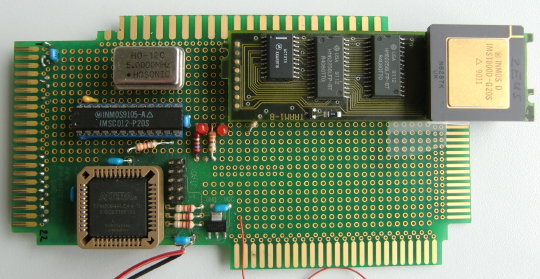
The T2C64 prototype in its full glory:
A short overview what’s on the card:
The left edge is the connector to the C64s expansion slot (ignore the other edges).
The square black chip is the Altera CPLD mainly containing the bus-interface and the Transputer Analyze/Reset/Error signal handling. Ah, and it controls the 2 LEDs.
The long black chip above the CPLD is an Inmos C012. This guy interfaces an 8bit parallel bus to the serial Inmos link ‘bus’.
The silver thing is a 5MHz oscillator to clock the C012.
And finally the longish module at the top edge is a TRAM with 128KB RAM and a mucho-macho T800 Transputer.
The CPLD maps the C012 register into the memory area of 0xde00, using just 6 addresses:
Data in 0xde00 (56832)
Data out 0xde01 (56833)
in-status 0xde02 (56834)
out-status 0xde03 (56835)
reset/error 0xde08 (56840)
analyse 0xde0c (56844)
So programming it pretty easy, still, you have to read some Inmos manuals about the protocol etc… that said the next chapters will show you some code examples I’ve slapped together just to test the hardware. All sources and binaries (.D64 image) are available in a zip file over here, obviously most of that does not make sense without having a T2C64…
Read on in the next posts for demo-code and even a video. “uuh, videos!”
Mind that were little endian and BASIC is using decimal numbers. So we’re POKEing 0,0,0,128 which is 0x00, 0x00, 0x00, 0x80 in hex which again is the 32bit address of 0x80000000.
59 PRINT"SENDING DATA TO T."

60 POKE56833,0:POKE56833,0:POKE56833,0:POKE56833,128

61 POKE56833,12:POKE56833,34:POKE56833,56:POKE56833,78

70 PRINT"I STATUS: ";(PEEK(56834)AND1)

79 :
Now reading back (PEEK) from 0x80000000 what we just wrote:
These 4 sequential PEEKs print 12 34 56 78. Yay! A very simple Ram-disk if you want.
Now something more serious. A very small programm is sent to the T and executed. Instead of peek and poke (1/0) the initial ‘command’ is the length of the program (23 in this case), so the T starts executing after he received the 23rd byte.
The program itself is trivial, after some initialisation it writes 0xAAAA0000 to link0out. The use of it is very simple. If the Transputer is working correctly the first 2 bytes will allways be “0xAA”, if it is just a 16bit Transputer (T2xx) there won’t be more than 0xAAAA. A 32bit Transputer returns the full 0xAAAA0000. Voilá, that’s a simple T-detection.
To handle timeouts end error conditions I had to do some ugly things in BASIC. Sorry, don’t blame me, BASIC v2 is just… very basic.
120:

128 DIM R(4)

129 PRINT"SENDING PROGRAM TO TRANSPUTER..."

130 FOR X=1 TO 24

140 READ T:POKE56833,T

150 WAIT 56835,1

160 NEXT X

170 PRINT:PRINT"READING RESULT:"

175 C=0

180 N=TI+50

181 IF C=10GOTO 220

189 IF TI>N THEN ER=ER+1:IF ER=10 GOTO 220

190 IF (PEEK(56834)AND1)=0 GOTO 189

195 R(C)=PEEK(56832)

200 C=C+1

210 GOTO 180

211 REM ------------------------

220 IF C=1 THEN PRINT"C004 FOUND"

230 IF C=2 THEN PRINT"16 BIT TRANSPUTER FOUND"

240 IF C=4 THEN PRINT"32 BIT TRANSPUTER FOUND"

1000 DATA 23,177,209,36,242,33,252,36,242,33,248

1001 DATA 240,96,92,42,42,42,74,255,33,47,255,2,0
Next up a bit more useful example, reading the Transputer executable directly from a binary file instead of having it in-line.
This example actually puts the Transputer to some sort of use… well, it’s still way beneath him but it does its job as an example.
Two tasks: a) Read the Transputer executable from disk and b) exchange data with the Transputer.
Here we go:
10 PRINT"INIT TRANSPUTER"

20 POKE 56840,0

30 POKE 56844,0

40 POKE 56840,1:POKE 56840,0

50 FOR W=0 TO 1000:NEXT W

60 POKE 56834,0

70 POKE 56835,0

80 REM READ STATI

90 PRINT "I STATUS: ";(PEEK(56834)AND1)

100 PRINT"O STATUS: ";(PEEK(56835)AND1)

110 PRINT"ERROR: ";(PEEK(56840)AND1)

140 PRINT"O STATUS: ";(PEEK(56835)AND1)
Up to here everything should be clear. Init Transputer, read stati -just to be sure.
Now we’re reading the executable (“GRAB”) from floppy and poke the bytes to the Transputer as they come flying crawling in:
150 DIM R(4)

160 PRINT"SENDING PROGRAM TO TRANSPUTER..."

170 REM READ TRANSPUTER BIN FILE

180 OPEN 1,8,2,"0:GRAB,S,R"

190 FOR I=0 TO 1 STEP 0

200 IF ST=64 GOTO 240

210 GET#1,A$:A=ASC(A$+CHR$(0))

220 POKE 56833,A

230 NEXT I

240 CLOSE 1
Ok, the Transputer binary expects us to tell it the number of integers we’re about to send to it (AN), the we send these (X) and finally re-read the results… which should all be X+7.
250 INPUT"COUNT:";AN

255 POKE 56833,AN

260 FOR AA=1 TO AN

270 PRINT"ENTER ";AA:INPUT X

280 POKE56833,X

290 NEXT AA

295 PRINT"GETTING";PEEK(56832);" RESULTS"

300 FOR BB=1 TO AN

310 PRINTPEEK(56832);

320 NEXT BB
Some final words about Transputer executables. There are many kinds depending which development system was used. Some need special loaders or bootfiles before the actual binary will be send to the Transputer. A ‘raw’ upload is only possible with binaries mostly having the extension of “.btl” (BooTfromLink). AFAIK only the OCCAM SDK and the Inmos C-compiler ‘icc’ will create those executables.
For those geeks who actually (still) do know their OCCAM, here’s the source of GRAB:
PROC first(CHAN OF BYTE in, out)
  #USE "hostio.lib"

  BYTE data.in, data.out :
  INT count, temp :
  [1000]BYTE array :

-- {{{ start main SEQ

  SEQ
    in ? data.in
    count := (INT data.in)
    SEQ i=0 FOR count
      in ? array[i]

        -- {{{ inner loop

            SEQ i=0 FOR count
              SEQ
                temp := (INT array[i])
                temp := temp + 7
                array[i] := (BYTE temp)

        -- end of inner loop
        -- }}}

    out ! (BYTE count)
    SEQ i=0 FOR count
      out ! array[i]
    in ? data.in       -- debug only
    CAUSEERROR()

-- }}}

:
And now something which you knew it would come: Mandelbrot time! 😉
I don’t want to bore you with all the details before you had it seen in action… so here we go:
“Man, that was brilliant! And even you had a lot of geek-babble in there, I want to know more!”
Ok Timmy, let’s go into detail…
Like I said in the video, the Transputer is finally doing something for real, he’s actually doing the most of the work, crunching through a 320x200x8 Mandelbrot, 32 iterations in double-precision floating point. The code itself was written 1988 in OCCAM by Neil Franklin and is available on his page.
This shows the general beauty of Transputers: If the code is written flexible enough to fit into any topology, it’ll run on any platform!
That said, I ran into a certain limitation on the C64. The Transputer mandelbrot executable expects the initial data (resolution, coordinates, iterations) to be send in a specific order and format. While the order isn’t the problem, the format is: The coordinates have to be doubles (C-lingo i.e. 64bit IEEE 754 compliant float). The C-Complier I’ve used for this demo (CC65) doesn’t now a flying s*** about floats or even doubles.
So to get that demo done ASAP I tricked myself a bit and used the same technique we’ve seen in my 1st demo when POKEing something the Inmos-way:
To get the coordinates for left (-2.0), right (1.0), top (1.125) and bottom (-1.125) over to the Transputer they had to be converted into 64bit IEEE 754 format, ordered into little-endianess and finally put into an array like these:
Yes, that’s a bit awkward, but it was OK to get a fast start. The ‘problem’ with this quick-hack is that the demo is pretty static, i.e. no zooming into the Mandelbrot. If you know of a quick way to create IEEE 754 compliant doubles from a long (which is the biggest floating point variable CC65 can handle, so StringToDouble() isn’t an option here) I’m happy to hear from you.
Of course I could have the Transputer do the typecasting but in this case, as part of a demo, I wanted to keep the original binary untouched.
In the video you saw (or didn’t because of the blurry picture) that the timer printout was about 70s… and as said, normally it takes about 60s to complete the fractal – and it did in the video, too! Watch the video-timer or check with a stopwatch. What I’ve forgot to take out from the timing was the actual upload of the code into the Transputer.
The Transputer binary is in this case a bigger array in the C-source, so it’s not being loaded from floppy but directly pushed to the Transputer after it was initialised. This takes some extra time which also went into the stopwatch timing… I’ll correct that in a later version.
“Later version” is a good catchword. If this wouldn’t be just a demo for now, there are obviously plenty of ways to optimise things:
First of all one should take off the burden of converting the colors from the C64 and let the Transputer do that.
My second idea would be to reduce the communication overhead (polling) by having the Transputer to render the whole screen into his own RAM and when done have it ‘pumped’ down to the C64
Yes, DMA would be cool but that’s not possible (yet)
Ok, that’s about it for now. The T2C64 is still in its prototype stage and I can image many more cool things to add… but first I will have a ‘proper’ circuit board being made.
Final words: Don’t get too excited about the acceleration of the C64… it’s not accelerated at all. It’s more like a co-processor attached to it. And even then, you’ll need something really calculation-intensive to justify the time you’ll loose due to communication between the C64 and the Transputer. A single square-root for example wouldn’t make sense at all. 100 sqrts in one go would certainly do.
Of course adding another linkOut/In to the T2C64 to get more Transputers involved into the calculation would be the final step. This is planned for the next version of the hardware but the bigger part of the work would be a complete rewrite of the Mandelbrot code to have it broken down to parts being run in parallel on each Transputer… which closes the loop to today where programmers are trying to wrap their brains around multithreaded programming. 22 years after the first Transputer was released 😉
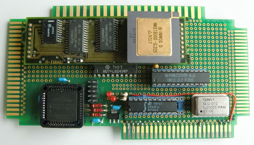
Ok, here it is. The T2A2. What sounds like a robot from StarWars is actually a Transputer to Apple II interface. Its design is pretty much the same than its cousin, the T2C64, with the addition of some buffers to behave like a good citizen of the Apple-II bus. So this is how the little beast looks as of now (v0.5):
To use the Apple-II bus-connector of the 8Bit-Baby (another brainchild of mine), I had to shuffle the parts around a bit. On top you’ll see the same TRAM used on the T2C64… 20MHz T800 Transputer, 128KB SRAM. Right below it is an LS245 octal bus-transciever to handle signals like DevSel, R/W and A0-3. To its right its the IMS012 Linkadapter converting 8bit parallel bus into INMOS’ serial link-protocol. Below that, there’s the silver 5MHz oscillator to clock the IMS012 as well as the Transputer and another 245 to buffer the data-lines (D0-7). Finally on the left bottom there’s the CPLD which handles the Analyze, Reset and Error lines of the Tranputer as well as chipselect and such (Thanks to Mike for helping out on VHDL here!).
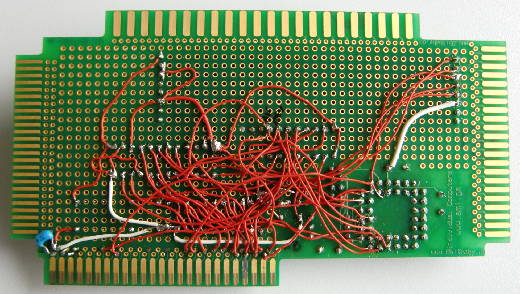
The picture above is the first Prototype and it’s finally working… even it’s a nightmare to look at its back side 😀
But because I’m a Commodore guy who wasn’t able to afford an Apple II in its hey-days I had to start from scratch and learn a lot…
That said, when I finally could afford an Apple II system, I went straight for the IIgs. I think IIgs is the perfect platform for an 8-bit Transputer interface given the amount of available/adressable RAM, native access to harddisks and a decent screen resolution.
Because of its simple design, the T2A2 should also work in any Apple-IIe etc. There’s no ‘firmware’, no EPROM. Just plain simple reading and writing to some (slot)specific addresses.
Due to its close relationship to the T2C64, programming is quite similiar. As a matter of fact I just slightly changed the examples I’ve used on the C64… which is the beauty of the idea.
So jump to the next post to see the first little test proggie in AppleSoft BASIC…
Like with the T2C64, the CPLD on the T2A2 maps the C012 registers into the memory area of the used slot, using just 6 addresses starting at 0xc080 + (SLOT# * 0x10). So for e.g. Slot 4 this would be:
BASE (0xc080 + (4 * 0x10)) = 49344
Data in: BASE 49344
Data out: (BASE + 1) 49345
in-status: (BASE + 2) 49346
out-status:(BASE + 3) 49347
reset: (BASE + 8) 49352 (writing)
analyse: (BASE + 12) 49356
errorflag: (BASE + 8) 49352 (reading)
With this ‘knowlege’ we can start talking to the Transputer… and to make our first babysteps we’re using BASIC. It’s pretty much the same code as used on the C64 with the exception that there’s no “elegant” timeout handling due to the missing clock in AppleSoft, so you have to wait a bit longer until you get the printout in the end.
For details about what’s going on here, see the C64 page.
 10  PRINT "INIT TRANSPUTER"

11 BASE = 49344:IN = BASE:OUT = BASE + 1:IS = BASE + 2

12 OS = BASE + 3:RESET = BASE + 8:ANA = BASE + 12

13  POKE RESET,0: POKE ANA,1: POKE RESET,1

20  REM CLEAR I/O ENABLE

21  POKE IS,0

22  POKE OS,0

30  REM READ STATI

31  PRINT "I STATUS: ";( PEEK (IS) AND 1)

35  PRINT "O STATUS: ";( PEEK (OS) AND 1)

40  PRINT "ERROR: ";( PEEK (RESET) AND 1)

45  PRINT "SENDING POKE COMMAND"

46  POKE OUT,0

50  PRINT "O STATUS: ";( PEEK (OS) AND 1)

58 :

59  PRINT "SENDING DATA TO T."

60  POKE OUT,0: POKE OUT,0: POKE OUT,0: POKE OUT,128

61  POKE OUT,12: POKE OUT,34: POKE OUT,56: POKE OUT,78

70  PRINT "I STATUS: ";( PEEK (IS) AND 1)

79 :

80  PRINT "READING FROM T."

90  POKE OUT,1: REM PEEKING

100  POKE OUT,0: POKE OUT,0: POKE OUT,0: POKE OUT,128

110  PRINT  PEEK (IN); PEEK (IN); PEEK (IN); PEEK (IN)

128  DIM R(4)

129  PRINT "SENDING PROGRAM TO TRANSPUTER..."

130  FOR X = 1 TO 24

140  READ T: POKE OUT,T

150  WAIT OS,1

160  NEXT X

170  PRINT : PRINT "READING RESULT:"

175 C = 0: REM RETRIES

180  IF C = 10 GOTO 220

181  FOR X = 0 TO 5000: NEXT X: REM DELAY

189 ER = ER + 1: IF ER = 10 GOTO 220

190  IF ( PEEK (IS) AND 1) = 0 GOTO 181

195 R(C) =  PEEK (IN)

200 C = C + 1:ER = 0

210  GOTO 180

211  REM ------------------------

220  IF C = 1 THEN  PRINT "C004 FOUND"

230  IF C = 2 THEN  PRINT "16 BIT TRANSPUTER FOUND"

240  IF C = 4 THEN  PRINT "32 BIT TRANSPUTER FOUND"

250  IF C = 0 OR C > 4 THEN  PRINT "COULD NOT IDENTIFY""

1000  DATA 23,177,209,36,242,33,252,36,242,33,248

1001  DATA 240,96,92,42,42,42,74,255,33,47,255,2,0
Ok, if this is running fine, i.e. a Transputer was actually found and your Apple didn’t went up in smoke, we’re set for some serious numbercruncing… and a video! Yay! We love Videos, don’t we?
Like with the C64, this is probably the reason you came here:
The friggin’ fastest Mandelbrot displayed on a IIgs, ever! 😉
Yeah, you’re right, it’s not the fastest Mandelbrot calculated by an IIgs (its very own 65c816 CPU, that is)… but hey, it’s still kinda cool – and sooooo much faster!
Okey-Dokey, here we go, a complete Mandelbrot in 60s. This time in color… and zooming in! I couldn’t do that on the C64 as the C-Compiler didn’t natively support IEEE754 doubles (like Orca-C does) and having a mouse also helps a bit, too:
Wow, that was nice, wasn’t it?! (Sorry for the shaking, need to get a tripod soon)
Especially when you take in concern how ‘far’ the native 65c816 code got during the video on a ‘sped-up’ 10MHz TransWarp GS.
Like with the T2C64 version there are surely several things which could be improved, but the IIgs (even at native speed) is well capable to handle the little bit of extra work. The limiting factor is the bus-speed, i.e. how quick the Transputer can push his data into the host (IIgs). You can clearly see that by the time it took the display the 3 zooms: They all took about 60 seconds, even each zoom means more calculations as the iteration is doubled each zoom, in this case 32, 64, 128.
The Orca-C source/binary of this demo -and the previous AppleSoft sample- is available here (zip’ed PRODOS disk-image). It won’t make much sense without a T2A2 and is GS/OS-only as it uses QuickDraw II and the EventManager (for mouse & keyboard).
Final words: Don’t get too excited about the acceleration of the IIgs… it’s not accelerated at all. It’s more like a co-processor attached to it. And even then, you’ll need something really calculation-intensive to justify the time you’ll loose due to communication between the Apple and the Transputer. A single square-root for example wouldn’t make much sense.
But OTOH, that’s exactly things are handled with the Innovative Systems FPE (using a M68881). So it might be worth evaluating. Maybe I’ll write a SANE driver if I have the time to get a deeper understanding of GS/OS.
As my two targets (C64 & Apple II) are working now, I’m thinking about creating a ‘real PCB’ in the medium term. Given the rarity of the Link-Adaptor (Inmos C012) I’m currently looking into the possibility to use a larger CPLD to move the C012 into that. This would actually make this ‘project’ a product to buy. But don’t hold your breath, need to get an eval kit first. Then some 100 days of fiddling, cursing and crying… and then more.
Again, a man had to do, what a man has to do…
My good friend Udo gave me some Transputers in QFP package, most of them previously used and unsoldered from some PCB. Nobody knows, if they are still OK or already braindead – so I needed a QFP Adapter.
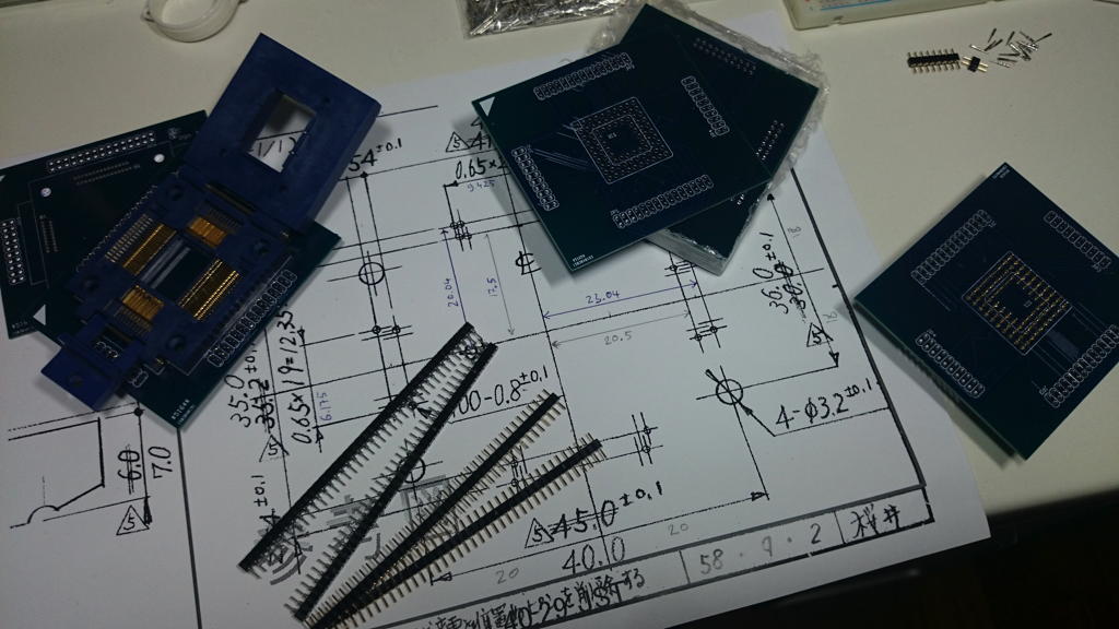
As fate goes, some fine day I stumbled across a nice 100pin QFP burn-in socket from Yamaichi on ePay. Yamaichi is “the other company” producing burn-in sockets besides 3M with their Textool brand range.
Normally those sockets are insanely expensive (100US$++) but this was a lucky buy – well for the “price” that it was an EOL model… for many years. This means no documentation available. But the very kind sales team of Yamaichi Germany (Vielen Dank Frau Howe!) was able to dig out a hand drawn blueprint of this very socket, model #IC51-1004-139.
This valuable Information at hand I was able to create my own Eagle CAD device for this Socket – not an easy task as most measures were not directly given but had to be calculated using other documented distances. After some hours I ended up with two PCBs, one for the burn-in socket which again will be mounted onto a PGA-Pin adapter PCB.
When done it was time for another “first”: Try the DirtCheapPCBs service. 2 Layers, 10x10cm PCB, 10 pieces for just US$25 (incl. shipping) – almost cheaper than doing it yourself.
After two and a half weeks I had two stacks of 10 PCBs each. Anxiously I tried if the socket with its tiiiiiiny pins will fit…. and… it… did! Hooray!! I didn’t expected that but everything fit perfectly, even the silkscreen. Soldering the 0.025″ pitch was another story…
But see for your self. Upper left corner you see the burn-in socket already soldered. At the right edge, the lower PCB it waiting to get 84 Pins soldered for the PGA socket… and another 100 to connect to the upper PCB.
Feel free to contact me, if it happen to be that you also found an IC51-1004-139 socket and need the Eagle lib or even the PCB for it… I have 9 of them left 😉
While the guys over at OpenApple were speculating in their latest podcastwhat a Transputer actually is… well, there are about a 100 links and ways on this page to find out – but hey… just click here – and of course that box saying search would do great wonders, too.
But seriously, my bad: I should have mentioned that this page your looking at is really just one post of many… so make sure you start at a Chapter (Menu. At the Top. ↑…yes up there) and read them in the order you’d read a book 😉
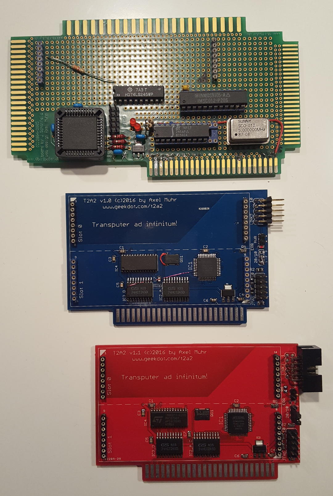
After quite some years (and a handful Apple II users requests) I felt the urge to finally put the T2A2 prototype (read that post to get a more general understanding) into a real expansion card… and here it is: Say “Hello!” to the T2A2 version 1.1!
It came a long way…
…in more detail:
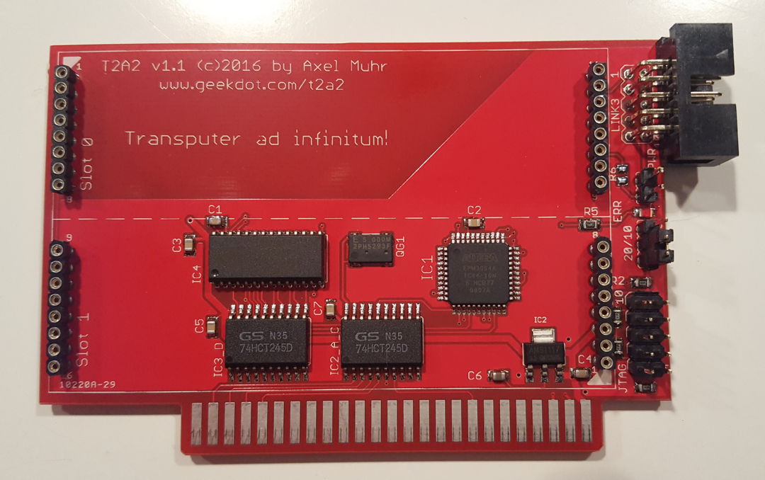
As you can see, the final T2A2 is much smaller than the prototype (which used an 8bit Baby one-for-all PCB) and offers many additional features
2 size-1 TRAM slots (or one size-2) – double the processing power!
Low-power, low-profile parts used where possible (3.3V CPLD, HCT logic)
External Transputer-link available as edge connector – extend your network to “near infinitum“
Jumpers for LinkSpeed and optional power to the Transputer-link connector
Fully buffered to be a good Apple II bus citizen
Works in any slot set to “your card”
Beyond this, everything said about the prototype is still true.
Most important:
a) It’s not tested in the ][ or ][+. I simply don’t own one of those. Update: One owner reported it’s perfectly working in his IIe!
b) The T2A2 won’t instantly speed up any of your Apple II[e/gs] applications.
It’s more like a co-processor attached to it. And even then, you’ll need something really calculation-intensive to justify the time you’ll loose due to communication between the Apple and the Transputer. A single square-root for example wouldn’t make much sense – but having a complex algorithm (like the Mandelbrot fractal in my demo) does absolutely make sense, as you just pass the parameters to the Transputer and let him do the sweating.
But on the other hand, FPU cards like the Innovative Systems FPE (using an M68881) or my even faster clone “NumberCruncher Reloaded” did just send instruction by instruction. So I somehow fancy the idea writing a SANE driver for GS/OS to integrate the T2A2 more transparently.
Want your own T2A2?
So now you’re keen to get one yourself? Please check this list first:
Do you have a TRAM already? (*)
You are aware that there’s no real software (yet) besides my little Mandelbrot demo?
You are keen to program something yourself – or are fine to wait until somebody else did?
While the Apple II side of coding is pretty easy, you have to get a grip about the Transputer development, too. That includes a DOS/Windows (<=XP) setup and some knowledge of C and/or OCCAM. I’ve created a little Transputer “SDK”, namely a VirtualBox image running DOS.
Ok, so you’re still with me… so I have the first batch of 20 T2A2 PCBs ready which I will populate on-demand, and for 40€ (plus shipping) one of them can be yours. (*) I might be able to offer you a TRAM, too. The price depends on available model, RAM size and CPU used.
⇒ drop me a mail to (Sorry, you have to type that into your mail-client – nobody likes SPAM, so do I)
Also check the T2A2 forum for current availability, shipping procedure and built status.
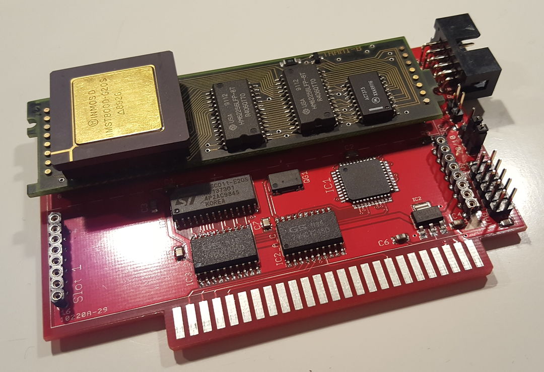
Some more technical details
Here’s a T2A2 with a size-1 TRAM installed in Slot-0:
The T2A2’s CPLD programming can be updated any time through a JTAG port (the lower 2×5 pin-row at the edge).
The jumper above it can be used to set the linkspeed for the TRAMs (10 or 20mbps). If you look very close, there’s a tiny LED next to that jumper. It’s the error LED controlled by the CPLD.
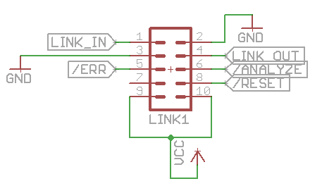
The next single jumper enables the VCC pins on the external Link connector, meant for (small!) external extensions. This connector is the same used on the Gerlach card and is very convenient because of its ubiquitous standard 2×5 shrouded pcb header connector. Here’s the pinout:
As said, the V1.1 T2A2 offers two size-1 TRAM slots. Before plugging in 40MIPS of raw processing power consider the amount of juice being pulled there. Depending on the amount of RAM and load a single TRAM can use up to 800mA of power! 😯
Given the max. of 4A on a standard IIgs power-supply, two TRAMs could bring your souped-up GS into trouble… it’s better to use the external connector with just one smaller TRAM or even simply bridge the Link0In/Out pins with Link3In/Out so that the T2A2 works as a TRAM-less adapter.
That said, there are size-2 TRAMs in existence which will snugly fit and won’t hurt that much.
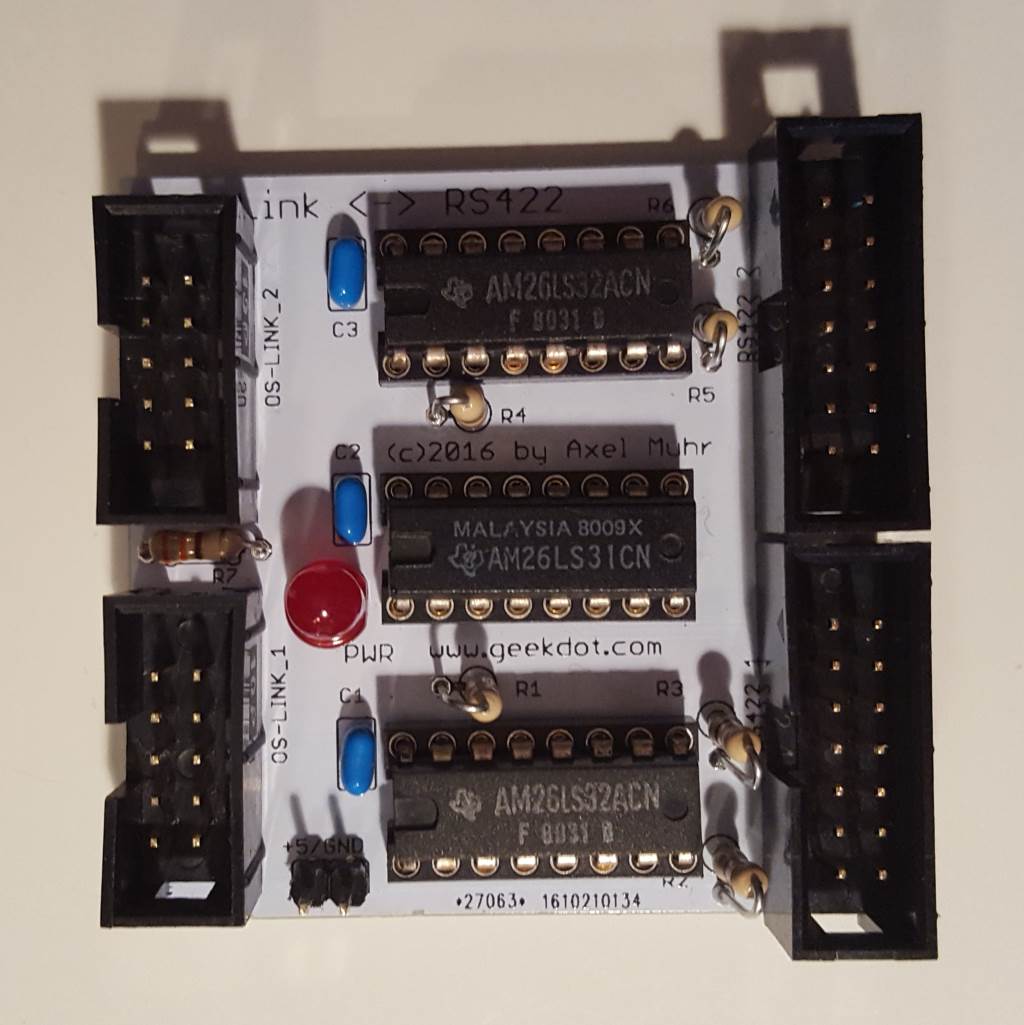
This is a Q’n’D but handy design which I was planning for a long time, but you know how things go… A differential adapter is a simple device which translates a single signal/data line in one positive and one negative line, i.e. one is carrying the inverted signal of the other. This is also known as RS422… But why do we need such thing?
Well, differential signals are/were quite common in the world of Transputing to deliver OS-link signals over longer distances (<10m/30ft) or noisy environments and good examples are systems from Parsytec, the AVM-T1, ISA interfaces like the HEMA TA2 or even some custom measure/data-logging solutions.
So to connect to such systems using a non-RS422 (i.e TTL) interface card, e.g. the INMOS B004/008 or the Gerlach-Card you’ll need such an differential adapter.
Technical data
A very simple design on a 5x5cm PCB. All done in trough-hole technology (THT) to keep this a simple DIY project.
It all based around two AM26LS32 receivers and one AM26LS31 transceiver, some resistors and an unavoidable LED 😉
Usage is very simple, too. Just connect the TTL signals to the standard 2×5 shrouded PCB header connector and RS422 signals are provided on the 2×7 header connector on the opposite side of the PCB.
The TTL connector is the same as the one used on the Gerlach card or my T2A2 Apple II interface:
As you can see, pins 9 & 10 can provide 5V to the PCB so that no external power-supply is needed.
If you connect a system not able to provide power to the differential adapter there’s also a 2pin connector provided on the PCB itself.
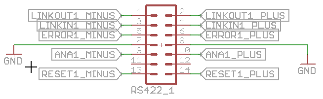
The RS422-side of the adapter has this pin-layout:
Nice-to-know: You could also use this adapter to simply invert signals. For example if you need a positive ERR signal instead of the not’ed, you simply take the positive pin (i.e. even pin-number 6 in this case) of the 2×7 connector (ignoring the negative).
Mind there’s no power supply pin on that side and pins 11/12 are not connected.
home of real men's hardware
We use cookies on our website to give you the most relevant experience by remembering your preferences and repeat visits. By clicking “Accept”, you consent to the use of ALL the cookies.
This website uses cookies to improve your experience while you navigate through the website. Out of these, the cookies that are categorized as necessary are stored on your browser as they are essential for the working of basic functionalities of the website. We also use third-party cookies that help us analyze and understand how you use this website. These cookies will be stored in your browser only with your consent. You also have the option to opt-out of these cookies. But opting out of some of these cookies may affect your browsing experience.
Necessary cookies are absolutely essential for the website to function properly. This category only includes cookies that ensures basic functionalities and security features of the website. These cookies do not store any personal information.
Any cookies that may not be particularly necessary for the website to function and is used specifically to collect user personal data via analytics, ads, other embedded contents are termed as non-necessary cookies. It is mandatory to procure user consent prior to running these cookies on your website.