Category Archives: MIPS

MIPS Hardware

miroHIGHRISC & miroTIGER

This is indeed a very rare breed – I was informed that less than a 100 of those were sold. Built in the end of 1992 as “Project Zorro” by the German company miro (bought by Pinnacle in ’97) it took the same line as all the other accelerated graphic cards in those days: Highspeed graphic -mostly TIGA- plus some speedy general purpose CPU. The SPEA cards using Intels i860 were direct competitors for example – I was also told that miro also looked into using the i860 but scrapped that attempt in an early stage in favor for the HIGHRISC.

The Miro HighRisc -or miroHIGHRISC as they wrote it back then- was a full-length 16-bit ISA card containing a MIPS CPU and a maximum of 32MB of RAM.

Technical facts:

  • 33MHz LSI LR33050 CPU which is a R3000 clone including the R3010 FPU minus MMU
  • 1k data- and 4k instruction caches on-die
  • 33 MIPS / 33 MFLOPS
  • 8-32 MB RAM plugged into up to 4 SIMM slots
  • 32 bit bus to connect the miroTIGER graphics card (100MB/s)
  • 2D: 150000 Vectors/s of 10 pixels length
  • 3D: 10000 triangles/s of 100 pixels, flat-shaded
  • 6000 triangles/s of 100 pixels, Gouraud-shaded

miro claimed that the HighRisc would deliver nearly twice the performance of an i860/33 solution with “real-world” applications (namely AutoCAD 12). That has yet to be proven but sounds reasonable given the limitations the i860 had when used as general purpose CPU.

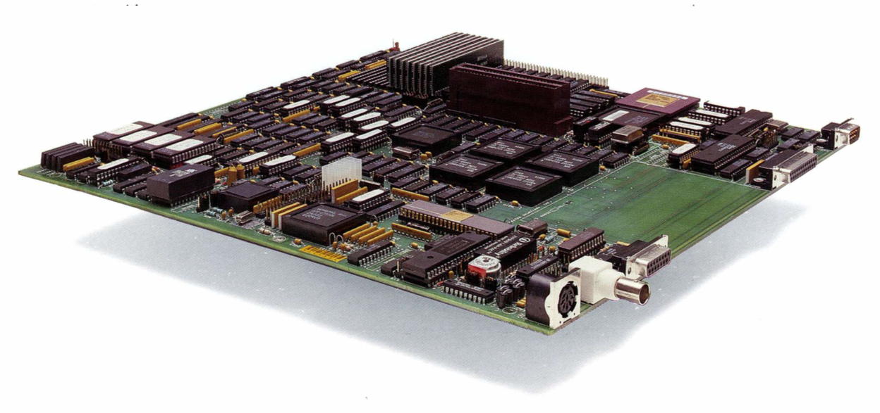
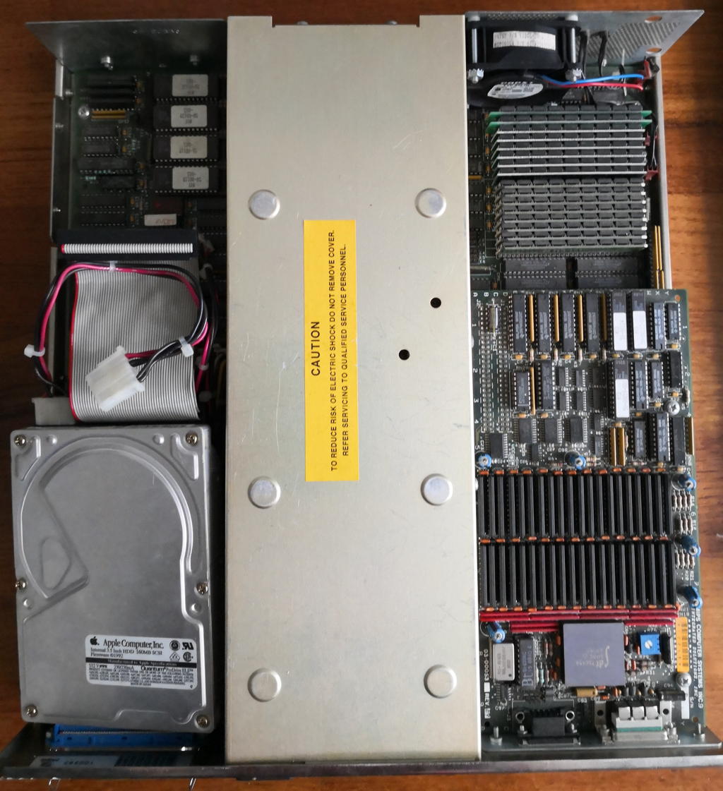
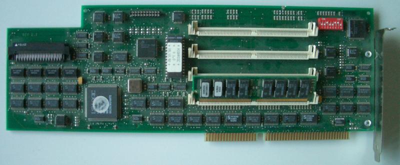
Here’s the HighRisc in its full glory:

HighRiscTotal

Interestingly, there’s next to none information on the Web about this card. Probably due to its high cost (5700DM) and the failing TIGA standard.
Here’s a nice snippet from an interview (in German) from 1999 with the original product manager Frank Pölzl:
Q4. What was your biggest flop?
miroHIGHRISC, a 3D-graphic card with MIPS and TI-Graphic-Processor.

Another tasty detail is that according to a news-snippet from the German magazine c’t (12/99, p.22) this card was developed in cooperation with Silicon Graphics (SGI) which bought MIPS some years before. Maybe this was SGIs first and last attempt to get a foot into the PC market?
Yet another interesting fact: The LSI 33k CPU was later radiation hardened by a company called Synova Inc., rechristened as “Mongoose V” and as such traveled into space several times… even to Pluto!

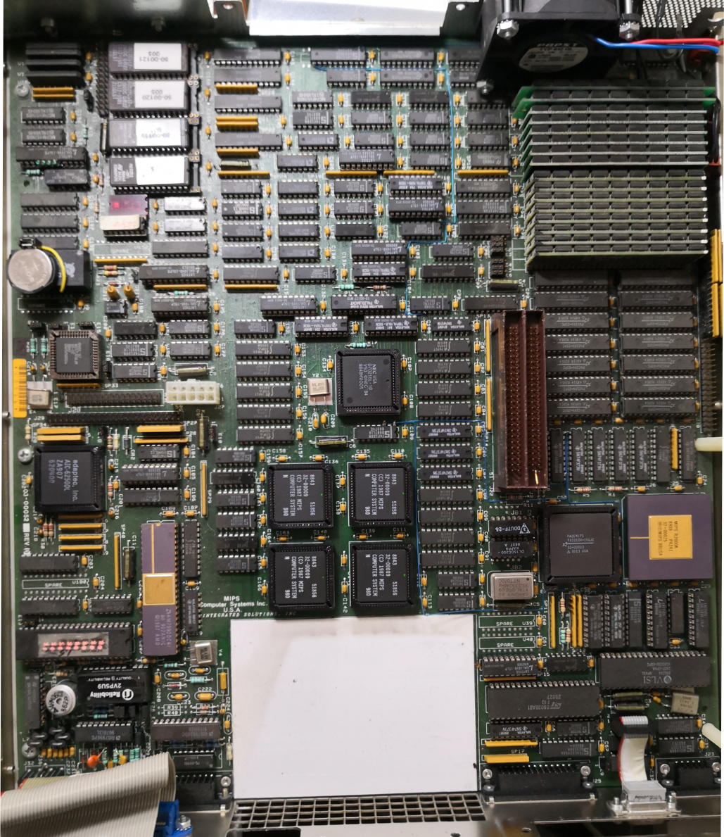
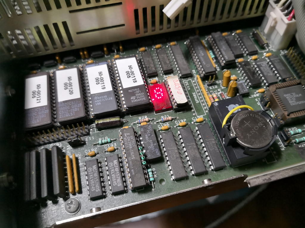
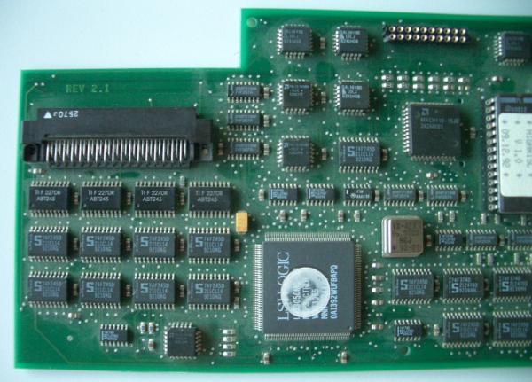
Here’s the left side of the card in more detail. It contains the CPU and the BIOS (32k EPROM dump available here) lots of 74-logic ICs, GALs and some MACH PLDs.
At the top-left corner of the picture below you see the connector to the miroTIGER, a TIGA graphics card described a bit further down on this page.
Also, there’s  an undocumented 20-pin connector at the upper-right edge of the card. This might be the 16MB/s interface “to connect peripherals like laser printers or repro-devices” as mentioned in the c’t article. Thinking about it – it’s an interface to an UART. This will be a nice project to do further investigation.

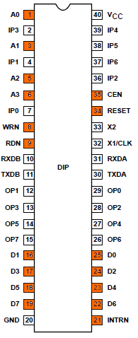
The pinout (the connector is rotated 90° clock-wise):

GND  oo  /WR0
D0   oo
      INT2
D1   oo  /RD
D2   oo  /IOSEL
D3   oo  (unknown)
D4   oo  A2
D5   oo  A3
D6   oo  A4
D7   oo  A5
VCC  oo  A23

HighRiscLeft

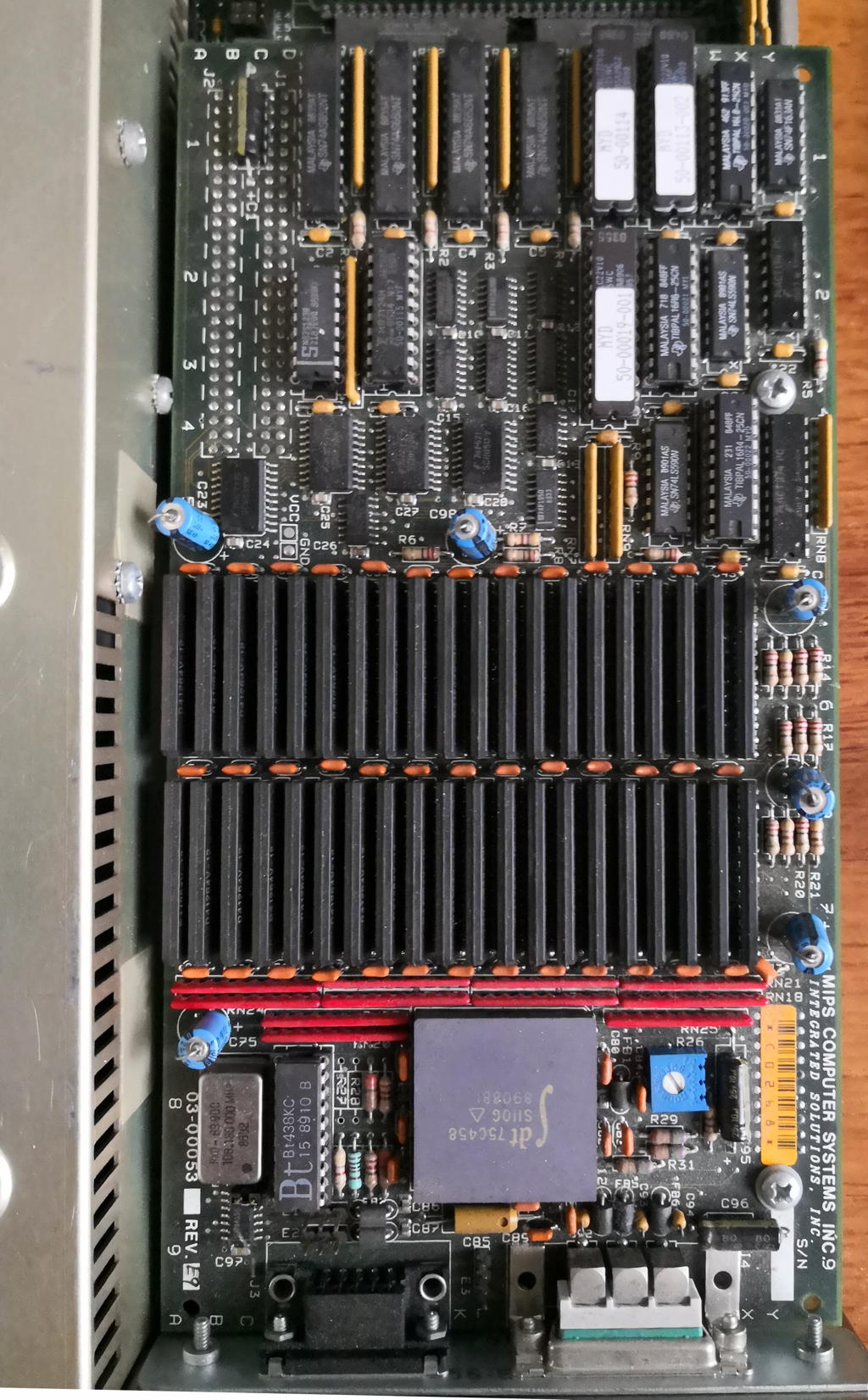
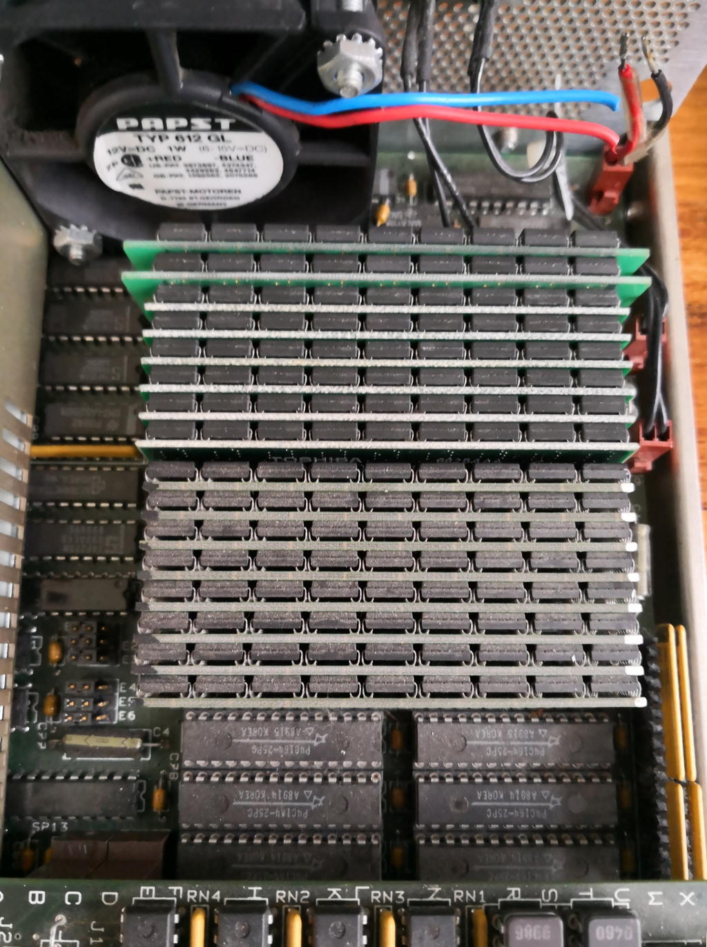
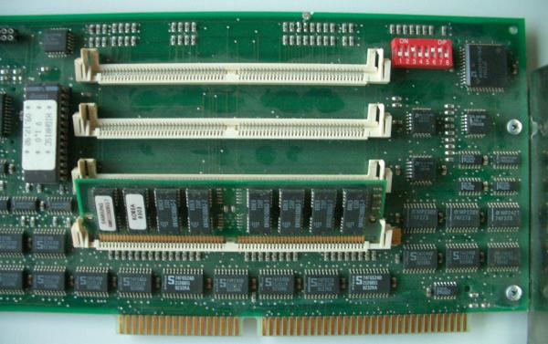
The right side of the card is dominated by the 4 SIMM slots which, according to the manual, support up to 8MB each. Also there’s a DIP-switch for setting up the address-range etc.

HighRiscRight

Even it has nothing to do with MIPS, the accompanying graphics card miroTIGER fits in quite good here. This card was meant to run for itself or accelerated by the above described miroHIGHRISC. This is what it looks like:

TigerTotal

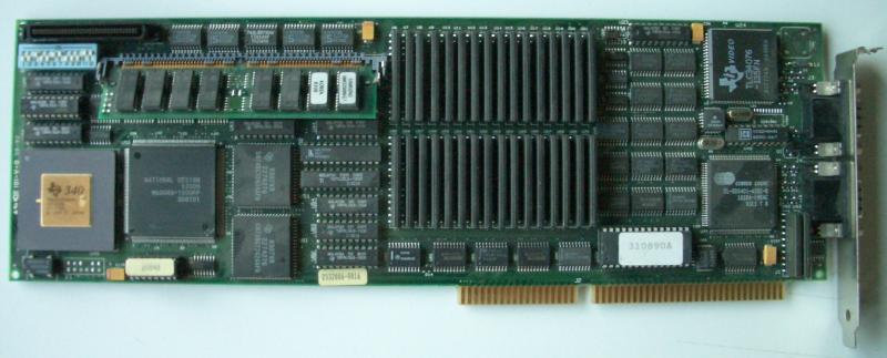
Following the TIGA standard it naturally features a TMS34020 graphics processor. This processor has its own RAM to do all the calculations, display-lists and fonts. Because TIGA was completely incompatible to the usual CGA/EGA/VGA standards you had to have such a card installed in parallel to see all the DOS/Windows outputs before switching into TIGA-mode. The normal setup was to have a 2nd high-res (1024×768++) monitor connected to the TIGA card then.
More advanced cards like the miroTIGER also had a VGA chip on-board, which saved you a slot and all the extra hassle. So let’s have a look at the details:

TigerLeft

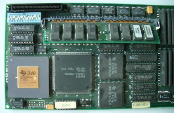
This is the left side of the card. The nice golden chip is of course the TIGA processor. Next to it there’s a National Design V2000 chip – most probably an ASIC doing all the RAM handling and stuff.. accidentally I stumbled across a notion of a “National Design Volante2000” TIGA card. Smell the relation here? So my most recent assumption about this is, that’s a somewhat standard TMS340 glue-chip, licenced by National Design to other TIGA card manufacturers.

The SIMM above is 8MB of RAM for the TMS340. Depending on the PAL (labeled 2004, 2044 or 2084) on the lower edge of the card, one could use 0, 4 or 8MB of RAM.
On the upper left corner is the connector to the miroHIGHRISC card as well as an impressive row of DIP switches.

TigerRight

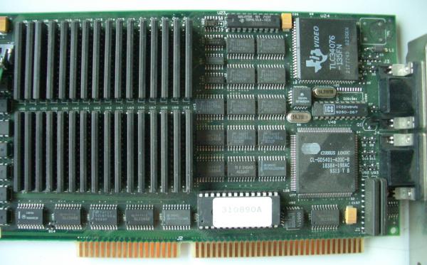
The right side is mainly occupied by 4MB VRAM for the TMS340 as well as the TI RAMDAC in the upper right corner.
Below is a very simple onboard VGA controller by Cirrus Logic (CL-GD5401 aka Acumos AVGA1) and next to it its puny 256k DRAM – which is the maximum a GD5401 can address by the way :-/

This is a good place to post a big thank you to Peter Huyoff – the wonderful guy who saved my life while doing the ‘research’ on this card.
As you might spot in the picture above, there’s one chip broken… a tiny 74AS74 flip-flop – try to find a single SMD AS74 these days. It’s impossible if you’re not prepared to pay $50 b/c of minimum order fees! And no, an F74 doesn’t do it, it’s still too slow. Been there, done that.

Peter provided me another working miroTIGER for free! That’s the spririt between real men! And Peter is definitely one of them!

Digging deeper into the highRISC

After 7 years mainly doing research on Transputers and the i860, I had the feeling it’s time to do some more digging into the highRISC card.
If you have read my initial post about the miroHIGHRISC (and the Tiger) you remember the undocumented 20pin socket on the card (pictured in the upper right corner):

HighRiscLeft

Let’s have another look at the “UART port” again:

The pinout (the connector is rotated 90° counter clock-wise):

GND  oo  /WR0
D0   oo  INT2
D1   oo  /RD
D2   oo  /IOSEL
D3   oo  RESET (most likely)
D4   oo  A2
D5   oo  A3
D6   oo  A4
D7   oo  A5
VCC  oo  A23

Reading a bit of the BIOS’ disassembly, I stumbled across routines to talk to an UART.  A very common (D)UART of those days was the SCN2681. If you take a look at this chips specs, they perfectly fit to the signals provided at the HIGRISCs UART-port!

Here’s its pinout with the corresponding pins marked:


A2-A5 are used for A0-A3 on the 2681 and the only pin not directly represented is A23 which might be used to decode. Also, it nicely reveals that CPU INT2 is used for the UART.

The LR33000 datasheet tells me that there’s an 4MB IO-area starting at 0x1E000000 reaching up to 0x1EFFFFFF- most likely the 2681 will live there… and the corresponding signal called /IOSEL is available on the UART-port (and will perfectly help as chip-select decoder). Tadaa!

So after the UART we need to get the RX/TX signals to a higher level, i.e. the +/-15V of RS232 – this is the call for our old friend MAX232.

[current bread-board experiments sadly didn’t yield into ‘instant success(tm)’… I’m missing out something – need more time to investigate]

Bootcode / BIOS

The LR330xx CPU also has an /EPSEL EPROM select signal, indicating it’s accessing an EPROM expected to start at 0x1F000000 and ends at 0x1FFFFFFF (4MB right below the IO-area).
Using this knowledge and knowing that the MIPS standard boot-vector is at 0x1FC00000, it’s easy to feed the ROM-dump I did some years ago into the disassembler with the correct start address to do his job.

We need to get an understanding of this bootcode first, so that we can get an idea of “what is where” (e.g. ISA bus, UART etc) and later upload our own code and use those addresses.
Just to stick my head a bit into the clouds, the aim is to first port a then common MIPS monitor-program called ‘PMON’ and use that to run some sort of μLinux. But that’s probably another handful of years ahead…
PMON was a good source of information, because it’s originally written by LSI, supporting all the LSI eval-boards. Lo and behold, some of them had a 2681 UART, too… located at 0xBE000000, which is extensively used in my BIOS disassembly  😉
I have a certain feeling that miro borrowed some design ideas from the LSI Pocket Rocket evaluation board (don’t Google it, it’s a mythic being – if you have documentation, mail me!).

So this is the 2681 memory-map then:

#define BASE_2681 0xbe000000
#define SRA_2681 ((1*4)+BASE_2681) // 0xbe000004 status register 
#define THRA_2681 ((3*4)+BASE_2681) // 0xbe00000C Rx/Tx holding register 
#define ACR_2681 ((4*4)+BASE_2681) // 0xbe000010 Aux contrl. register 
#define ISR_2681 ((5*4)+BASE_2681) // 0xbe000014 interrupt state register 
#define CTU_2681 ((6*4)+BASE_2681) // 0xbe000018 Counter timer upper 
#define CTL_2681 ((7*4)+BASE_2681) // 0xbe00001C counter timer lower 
#define START_2681 ((14*4)+BASE_2681) // 0xbe000038 start timer 
#define STOP_2681 ((15*4)+BASE_2681) // 0xbe00003C stoptimer

Using those addresses we should easily identify the comms routines.

Something happens at 0xBE800000 which seems not UART related. So that’s probably the reason why A23 is available on the connector. That way we can ignore access to that address by OR’ing it with /IOSEL to create a /CS.

The DOS side of things

The tool to load a MIPS executable into the HIGHRISC is called DL.EXE. Loading the test-program prints this to the console:

miroHIGHRISC download program. V 1.00
(c) miro Computer Products AG , Germany

CONFIG: I/O-register-address: 0x368 
CONFIG: DRAM - base-address : 0xD000 
CONFIG: DRAM - size : 8 MB
CONFIG: TIGER - RAM - size : 8 MB

Resetcount = 87340

Loading test.zor
text : start=0x80030000 size=0x52c0
data : start=0x800352c0 size=0x520
bss : start=0x800357e0 size=0x150
entry : 0x800301a0
TIGER comm.address : 0x3ffd00
max_used_address : 0x35930 
real_DRAM : 0x800000 
Heapsize : 0x7CA6D0

test.zor sucessfully downloaded.

This gives us valuable information. The DOS-side uses the IO port 0x368 and has a memory window of 16K from  0xD000 to D3FF.
MIPS programs are loaded to 0x80030000 and the 16K seems to be mapped to 0x003FFD00, just 128K below the 4MB boundary of the LR33k address space.

As usual – this is heavily work-in-progress. So this post will be edited while making any new progress. TBC…

The MIPS RS2030

Intro: The sleeping beauty

Well, the MIPS RS2030 isn’t really a beauty – but it slept quite a while in my basement. Actually, it’s a mediocre UNIX workstation at best… but there are many things about it, making it a special piece of my collection – and as an returning reader of GeekDot you may know I have a soft spot for those whacky things from back then… and as often with my posts, this one will be the most detailed you’ll be able to find. The RS2030 is yet another lonely system.
Well, if you look like this, you’re not the hottest thing in the Workstation-Discotheque 😉

First things first

MIPS… Even if you have just a dim knowledge about processor history, this name will ring a bell… Founded in 1982 MIPS created the first commercially available RISC CPU and until 1992, they were system manufacturers, too.
The RS2030 had many “firsts”: It was one of their first models, featuring their first CPU, the R2000, and somewhat paved their way into the market while immediately hurting MIPS’ reputation… more about that later. And last but not least, the used OS was one of the first 32-bit operating systems (1985) for RISC-based workstation-class computers.

So here are the specs:

  • Insane 12 (VAX)MIPS squeezed out of an 16.6MHz R2000 CPU and R2010 FPU. 32KB external Cache should speed things up a bit…
  • Up to 16MB (yes, that’s the max) RAM
  • 10Mbps ethernet… that’s 10base2 or an AUI transceiver.
  • 4MB/s synchronous SCSI interface (internal space for one 3.5″ HD)
  • Two RS232 ports controlled by an NEC V50.
  • Optional monochrome or color frame-buffer
  • Optional 3.5″ floppy drive

Just for the record: There was a 2nd model called RC2030, which only differed by not having the frame-buffer. It was sold as server… that’s why the put the “C” in the name. Errr, no, it’s… not… logical. So I’ll forget about this and move on.

The official brochure pictured all these parts like this:

Nice, but missing the power-supply and stuff… in reality, my RS2030 looks like this from the top:

Yeah, I’m missing the the hard-drive carrier – but the same goes for the front bezel, so what the heck… OTOH I have the mighty color frame-buffer, which you can see to the right of the huge power-supply in the middle. It is capable of 1280x1024x8bits/pixel at 60Hz. Here it is in more detail:

Here’s my mainboard having the PSU and frame-buffer removed, revealing the glorious R2000 and his math-bro’ R2010 as well as the V50 “I/O processor” and 4 mysterious MIPS custom chips :

Right behind where the frame-buffer sat, above the CPU/FPU you’ll find the L2 caches and RAM slots. These are SIPP modules and the maximum supported are 16x1MB.
Back in 1989 that was many… not much, but enough for a serious workstation:

Looking closely you’ll notice the cut cables for the 2nd fan (wasn’t me!). A small but very loud one meant to cool the RAM and most important the CPU/FPU underneath the frame-buffer.
Because I currently run the RS2030 without lid, it’s OK. But after some hours it gets quite hot in that region.

To the left of the power-supply (which has another very loud fan) are supposed two carriers for the hard-drive and the floppy-drive. Both were absent when I got this little beast.
Underneath the drives are the ethernet and SCSI controllers as well as the 4 EPROMs containing the “BIOS”, aka monitor.
Like all workstations back then, the RS2030 boots into a monitor, a basic software which gives you some means of setup and options to boot from HD, tape or network. More about this in the next chapter about setting things up.

To round things up, here’s the back side – connectors are from left-to-right:
Keyboard (DIN), 10base2 & AUI ethernet, SCSI, one parallel, two serial connectors and on top the frame-buffer. Mind the uncommon “0W3” RGB connector.

The OS with the many names

Finally, the RS2030 -like all MIPS workstations- ran a strange flavour of UNIX called UMIPS or MIPS OS or RISC/os or RISCos (not to be confused with Acorn Ltd.’s RiscOS)… all tree names/notations are used randomly across documents and mails from those times. So Googling stuff is a drag, 99% of the hits are Acorns RiscOS pages.
It seems MIPS’ operating system started out as UMIPS (UnixMIPS) and settled to RISCos around 1990.
As said, in 1992 MIPS gave up making computers… and was sold to Silicon Graphics (SGI). And playing around with early IRIX versions you smell RISCos all over the place – it’s definitely the mother (or father) of IRIX.

Anyhow, like other Unices of those times, RISCos is hard to get used to it as it misses all those comfortable things we got used to in these Linux days. No bash, no editor but vi etc… To make things short, here’s the Wikipedia roundup:
RISC/os was based largely on UNIX System V with additions from 4.3BSD UNIX, ported to the MIPS architecture. It was a “dual-universe” operating system, meaning that it had separate, switchable runtime environments providing compatibility with either System V Release 3 or 4.3BSD.

Rant, rant, rant…

As said in the beginning, the RS2030 wasn’t quite the showpiece for MIPS. During my research I came across many disgruntled posts about this and other MIPS machine(s).
It actually seems that the RS2030 wasn’t even designed by MIPS but taken over from some other company (my assumption is ‘Integrated Solutions Inc.’ given the marking on the frame-buffer) to fill a gap. Here’s the gist featuring replies by someone who obviously worked for MIPS back then:

>>Between the sloppy I/O implementation (the RS2030 was designed by a
>>now-defunct-or-nearly-so workstation company, whose design Mips had to finish
>>to allow the delivery on a large contract; the bozos who did the box used an
>>off-the-shelf NEC V50 chip for I/O and programmed it poorly, causing lame
>>serial and SCSI performance where simply using the R2000 would have worked
>>better), the lack of expandability and the proprietary memory modules…

The options at the time were:
a) Walk away from a deal for a few thousand systems, a large percentage at the time of Mips’ total base
b) Manufacture only the few thousand systems, and make little or no money on each because of economy-of-scale issues
c) Build and announce the 2030, and keep going on the next generation (albeit somewhat delayed)

(a) and (b) would have resulted in no Mips workstation product at all
that year, which would have been dramatically worse for the company.
The strategic direction at the time was to expect most serial i/o to
come in from terminal servers (this was subsequently modified somewhat).
In addition, issues of SCSI performance did not become apparent and reproduceable from quite some time after product launch.

>Surely MIPS could at least provide new ROMs for the V50? Or did the
>bozos solder them in?
There are some reliability fixes available. As for performance, let’s
face it: nobody’s going to spend money to improve the performance of a
system, at no return, years after it has been dropped from the product
line.

Wow, so it was deliver something mediocre and move-on quickly to create something better. IMHO not the best way to build a good reputation.
This probably led to comments like this:

Unfortunately, computers made by MIPS Co. were ill-engineered products. They were error-prone. From my limited experiences, they easily got broken. We had many broken RC2030s (early times RISC desktop with sloooooow R2000, codenamed “Jupiter”) and many broken RC3230s.
We stock them unwillingly and dumped eventually with disappointments.

Does this make me turning away from this poor little, mediocre thing. Not a bit! It’s an important piece of IT history – and because this is GeekDot, I will make it work for its money.

So follow me to the next chapter: RC2030 – The resurrection.

MIPS RS2030 – the resurrection

As mentioned in the first MIPS RS2030 post, I’ve got mine off ePay around 2004 and after some testing its life was about slowly moving through my basement waiting for it resurrection…

Hardware

The long way into the light

So, in 2004 the RS2030 wasn’t in the best condition: No front bezel, no hard-drive and a flakey DALLAS clock-chip. There were 8MB of SIPP modules plugged in and luckily it came with the original keyboard, a monitor cable and two QIC tapes from 1989 containing RISCos 4.10.
I fiddled around with it for a bit, still having a 21″ CRT on my desk, happily connecting to the BNC cable and the tapes were still readable but I wasn’t able to get things booting without a tiny bit of documentation. At least I added 8 more 1MB SIPPs for small money to fill it to the brim.

This changed 2012, when I got in contact with Julien Noël, who ran no-l.org (wayback-machine link) which pretty well described how to install RISCos. Well, he had a MIPS Magnum 4000 and used a bootp() server, but it described a lot of things I was desperately needing for my resurrection.
Some mails flew back and forth, a BNC-to-VGA adapter was build and little RS2030 saw some daylight again. Sadly my QIC tape-drive disintegrated over the last years and its pressure rollers turned into sticky goo – and I figured this out, when the goo slowly crawled into my precious tapes. Yikes!  😥
I cleaned the tapes as good as possible and everything went back into the darkness of “Zee Vault™” again. I think it was the next month, when Julian sent me a tarball containing RISCos 4.52 tape images. I saved them in a safe place and moved on…

Now or never!

This year (2018) I had more time at hand than usual and plenty of it went into some of my Macs and a comparably vintage SGI Personal IRIS.
During my fight practicing with installing IRIX 5.3 onto a clean drive I felt like prepared for an even older MIPS box. This time it had to be done! I got myself a new-old-stock QIC drive, 2 still sealed QIC-150 tapes and moved everything in front of my LG TFT display, which is able to handle sync-on-green signals.
Let’s check if it’s still alive at all – flick the switch, a noisy fan starts blowing and ~45sec and some beeps later the RS2030 is back in business:

Yes, the console looks strange. It just uses 2/3 of the screen and has a frame around it. The green tint is due to my way too long video cable.

Ok, there are many “FAILED” messages but it found all RAM and the ROM monitor (aka BIOS) prompt is happily blinking. Woohoo! I left it running/idling like this for a while just to make sure the power-supply stays stable.
After half an hour I moved on. The fails of the NVRAM and Counter/Timer test showed that the DALLAS DS1287 clock-chip finally went flat. The failed SCSI Master Test gave me a bigger shiver…

The clock-chip was quickly removed, the ram content saved, cut-open and enhanced with an external 3V button cell. It’s a common drill for all vintage hardware enthusiasts. I think this is the mother of all clock-chip modding posts.
Luckily the SCSI Master Test went away with the modded DS1287. Phew… while I had my beloved EPROM programmer at hand, I also saved the four 27c512 EPROMs and some Googling actually brought up a  more recent version than mine: v4.30 from Jul. 1989 vs. 4.32 from Jan.1991. You can download the binary images here. The most useful difference I found is the added ‘sprobe‘ command, listing all SCSI devices found.

There’s a nice thing all computers should (still) have. A 7-segment display next to the EPROMs giving you some idea of the systems status while booting. Also pictured the modded clockchip.

I found an older post of somebody desperately looking for a keyboard. While it looks like an XT-keyboard and weights like an IBM model M, it seems to be somewhat special. As said, I’m lucky to gave gotten mine together with the RC2030.

This was the last step: Check the drives. Find a proper SCSI hard-drive and externally connect my new tape-drive.
Having learned from my “tape disaster” in 2012 I carefully checked my tapes before putting them into my precious new tape-drive. And yes, they had a problem: The the slack retention belt was worn out and lost its elasticity…. resulting in, well, slack. To fix this you need a new(er) tape as ‘belt-donor’ and then do some tape-DJ’ing.

As I wasn’t able to find 2 reliable donor tapes, I decided to not dump the RISCos 4.10 tapes and move on…

Software

It’s getting serious: I took my two best blank QIC tapes and copied the RISCos 4.52 tape-images onto them using Linux on my retro-server (which one day deserves a post for itself). That was the easy part…

Let the game begin

Using Juliens recipe the initial boot from the tapes went smooth. Well, at least for 90’s measurement. Times were different, so it’s definitely not slap in some DVD/USB-stick and let the BIOS do the rest – choose some packages to be installed and baaam!, OS installed.
This is the drill (theoretically):

  • Use the minimal boot command of the ROM Monitor to boot a stand-alone shell (‘sash‘) from the 3rd block of the tape.
  • This sash knows filesystems, so you can use it to temporarily copy a mini-root system from tape block #4 into the swap-partition
  • Then load the RISCos kernel from tape telling him where to find the mini-root filesystem.
  • Finally this kernel loads a full-blown shell which then is able to execute the install script (‘inst’).

But if you’re not owning an original hard-drive you have to format/partition yours first. In this case you have to “boot” the MIPS format tool. It’s the grandfather of SGI IRIX’ fx, just even more basic.
Very 
basic. And confusing. Out of the box, it “knows” 13 hard-drive models, of which 8 aren’t even SCSI. And all of them are very, very, very obsolete. Here’s the printout:

Option #13 gave me some hope… “other” means you can add your own drive – if you have these specs at hand:

Well, I guess you don’t. Neither did I. So I wasted spent 2 days to figure out how to get a partition scheme and whatever else is needed by RISCos onto my disk.
To spare you this experience, bad ideas are:

  • Use the IRIX’ fx tool
  • Use gParted
  • experiment with those wiredo specs

The solution is -as most of the time- simple. Choose some SCSI disk from the menu, answer all questions but deny formatting, so it will write all partitions and the so-called volume header (a partition containing sash and stuff). The tool ‘prtvtoc’ (PRinT Volume Table Of Content) will then show you something like this:

After that you can boot sash, miniroot und finally start ‘inst’. Again a very simple installation tool which creates the EFS filesystem and copies all packages onto the hard-drive. Time for a break… tapes are slow and it’ll take ~2hrs.

So tonight I’m gonna party like it’s nineteen ninety-nine

When that’s done, you have to reboot and your MIPS will boot like a proper workstation… back in the days. It takes some minutes and it greets you with a simple ‘sh’ prompt.

To make your life a bit easier quickly enter ‘chsh’ to switch into ‘csh’ which is a bit more modern.
From there have fun exploring your new, old system. Ah, and don’t forget: RISCos is not year 2000 aware. So set the clock to something before December 1999 😉

Don’t miss the next chapter: Home improvement… making things a bit more convenient.