Tag Archives: repair

Dissection time!

Ok, as I’m probably the last person on this planet fiddling around with the NumberSmasher i860, it was either “help yourself” or bust.

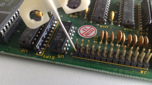
Given the fact that there’s an INMOS C012 on the card I tried my luck with the standard address of 0x150 and checked it with DOS’ crappy old ‘debug’. To my surprise I was able to talk to the C012, so it was very worth to investigate further.
So out went the good ol’ EPROM programmer and the EPROM of the card was dumped into a file.
I have 3 of those boards, two having a label on the EPROM saying “v1.1” and “BOOT_B2”. Both are identical… if you happen to own a NumberSmasher with a different label, get the dumpfile here for comparison.

That was easy, now the harder part: Disassembly. I had to revive my i860 machine language skills again, so it took me 2 days (on and off) to get a full understanding, what’s happening in there.
For those i860 assembly geeks among you, here‘s the fully commented code.

This “BIOS” is actually pretty simple. It’s just what I’d call a “PeekPokeStarter”. The main loop is waiting for a ‘command’ coming in by the way of the C012. This command can be either “0” or “1” as mentioned in the article on the previous page.

“0” means POKE (ie. write) and expects 4 bytes for the address and 4 bytes of data to be written (Both LSB first, Intel-style). So the full command reads: 0 00 00 00 20 78 56 34 12 or “write to address 0x20000000 the value 0x12345678”

So in consequence “1” means PEEK (ie. read) which just needs 4 bytes for the address to be read. The command would then be 1 00 00 00 20 or “read from 0x20000000”. The “BIOS” will then put 4 bytes to the C012 port at 0x150, which requires 4 reads from the PC side getting “78”, “56”, “34” and “12”.

Pretty simple, huh? But how can I start a program after it’s been painstakingly poked into the NumberSmashers RAM? Here’s the trick:

Poking to address 0x00000000 means start from the address given as data. E.g. “write to address 0x00000000 the value 0x20000000” is actually “start from 0x20000000”, or as command-chain: 0 00 00 00 00 00 00 00 20 – so beware of poking to 0!
Also, starting a program seems to disable the EPROM, so communication to the C012 is cut off if the running program isn’t handling this itself.

That’s about it. Nothing more in the “BIOS”… that’s why only 495 bytes(!) of the 8K EPROM are actually used. This simplicity leads to a very simple memory-map:

Base =  0xF8000000
C012-InData = [base] + 0x07
C012-OutData = [base] + 0x0F
C012-InStatus = [base] + 0x17
C012-OutStatus = [base] + 0x1F

Next task: Get a program running on the NumberSmasher.

[11/11/10] Great News…again! It was easier than expected… the first program running on the NumberSmasher-860! So read on in the next post…

Fixing scratched traces

This is the price you have to pay if you’re into real men’s hardware:

Being (falsely) identified as “old crap”, some cool things end up in the dumpsters… or worse. Being tossed around in some storage for years, probably stacked with other cards and boards, it might happen that some traces on the outer layers got badly scratched, thus making the board/card non-working. Here’s how I try to fix scartched traces… and most of the times it works:

First make sure that the circuit path (trace) is really broken – I just may look like, but isn’t.
To do this you need a volt-meter. Follow the suspected trace in both directions until you find a pin or through-hole it is connected to. Use these two points to test if the trace is still connected.

Ok, damn, it’s broken 🙁 You need three things:

  1. A sharp knife or scalpel
  2. Adhesive tape (Scotch, Tesa or whatever it’s called in your corner of the world)
  3. Conductive (silver) lacquer

Conductive-what? Conductive lacquer is actually a cool thing to play with… but be prepared: It’s not cheap (about 9-10 Euros). It comes in tiny bottles or as a pen, which is even more expensive (20+ Euros). The bottles look like this (lacquer and diluter):

ConductiveLacquer

Ok, the process is quite simple:

  1. Use the knife to scratch-off some of the coating lacquer on both ends where the trace was “cut” until you see some copper shining through.
  2. Check with your volt-meter that you actually have contact with one end and e.g. a pin on the other end of the trace. Do this for both “halves” of the cut trace.
  3. Mask the place you’re going to ‘heal’ with your adhesive tape – this prevents the conductive lacquer to run all over your board.
  4. Apply the conductive silver lacquer onto the spot you’ve just masked and let it dry (read the manual that came with the lacquer – yeah it’s unmanly but nobody will see you ;-))
  5. Using your volt-meter, check again. This time from both ends of the complete trace.

If you’ve done everything right, the  trace should work again – and so does your card/board! Yay!

Here’s how my badly scatched MiroHIGHRISC looks like in certain places – can you spot the little silver dot?

FixedPath

Final hit: Some lacquers are quite thin on silver (blame the manufacturer) so after some days the spot you just fixed might become unreliable. In this case you might repeat the procedure to get more silver to that spot.

Removing pin rows

Removing pin rows…doh! It took me quite some time to figure out a working solution for this problem, so I thought it might be useful to you some day, too.

Some idio^h^h^h^h not so clever person cut off all the pins on one of my DSM860 RAM boards – I probably will never figure out why (may a lightning hit him!). Besides 8 of the pins all other 74 (!) where cut, rendering the ram card non-functional (it’s the memory bus connector).

Here’s a (blurry enlarged) picture of the mess:

DSM860-RAMcard-Pins1

I started to desolder some pins from the back-side of the card but soon found out that the solder was too old to be removed the classic way (desolder pump & wick). Also, that pin-row (41×2) was one piece, so I would have to completely remove all the solder before I would be able to pull the part from the card.

After some thinking I came to this solution, which worked quite good:

First you need to cut away the plastic part from the top of the board. I used a very fine and sharp  caliper to cut away one pin after the other (i.e. like a single jumper).
While doing so be careful not to cut into the board!
Then pull or push the plastic pieces from the pins, again one after the other – I used a thin knife pushed under the plastic an gently wiggling it over the pin.

When done, it should look like this:

DSM860-RAMcard-Pins2

You may spot that some pins are missing already – that’s because my previous desolder tries sometimes seemed to work. Still, I couldn’t avoid that some pins got bent. This is the time for my secret repair tools: Syringe needles!

Second, get two kind of needles:  Gauge 18 and 20, that is 0.9mm and 1.2mm, color code yellow and pink. Cut off the tip of the needles and use a rasp to make the edge straight and clean. They should look like this then:

Needles

The bigger needle (G20) is just perfect to be completely pushed over a pin which then can be bent into any position without the risk of breaking it off – it works like this:

BendPins
(This is just a showcase picture with a different board, the needle needs to be pushed all the way down over the pin)

So straighten all the pins into an upright position. This will be important for the next step!

Now put your board into a vertical position (e.g. fixed by a bench vise or clamped between your inner thighs ;-)), get out your solder iron and the G18 needle – this needle should be just small enough to fit through a pin-hole.

This is the third and last step. Place the G18 needle over the pin you like to desolder on the back-side of the board like showed here:

PushPins

From the other side you’re touching the base of the pin with your solder iron. As soon as the solder starts to melt gently push the needle onto the pin.
If everything works like it did for me, you will push the needle through the board, including the solder and the pin you’ve planned to remove!

The great thing with this is that the needle (being made of steel) does not stick to the solder. As soon as the needle got a bit colder, you can easily remove the pin as well as the excess solder from the needle with your fingers!
Now carefully pull back the needle through the board and you should have a nice and clean through-hole in the board. If not, a final cleaning with a desolder-pump or wick should do it.

This needle-trick also works brilliantly with empty pin-holes which got filled with solder. Just place the needle on the pin-hole on one side of the board, heat up the solder on the other side while pushing the needle. Pop! There goes the solder!

As said, this technique worked great for me. All 82 pins got removed, a new pin-row was soldered into place and the card is now working like a charm.

Still, do this at your own risk!
I’m not going to be taken liable for any damage to your board or your health!
If your unsure if you are able to perform this stunt, don’t do it!
Practice with an old scrap board/card before you fiddle with the “real thing”!

DesperRAM

You might have been in the same situation: Some piece of old hardware could be upgraded (aka pimped) with more RAM, but there’s no place in the world to get that type of RAM needed.

In my case it was 1Mx4 DRAM in a DIL packaging. It’s hard to come by those in a ZIP packaging – sometimes used on AMIGA RAM cards – but DIL is next to impossible.

Well, when 1Mbit RAM chips were introduced, the industry switched to SIMMs anyway… and that’s where you find those. For the DespeRAM, SOJ packaging is what you want. SOJ (sometimes also called J-Lead) means there are short pins on the IC but they’re bend inwards under the chip… pretty much like PLCC pins.

What you need for this stunt:

  • Desperation. Lots of it.
  • A hot-gun (for getting the SOJ chips off the SIMM module)
  • A fine tip on your solder-iron. Very thin solder led (e.g. 0.5mm)
  • DIL sockets for your desired piece of crap^h^h^h^h vintage hardware
  • Wire, also thin (I used 0.6mm)

Preparation:

Clean desk. Good lighting. A steady hand (no coffee or drugs – I assure you, it won’t work. I tried it ;))

Ok, so first of all get out the hot-gun and carefully get the ICs off the module. Here’s a single chip and the socket it should be mated to

desperRAM1

Bend the pins and straighten them. I used a needle to pry the pins upwards a bit and did the rest with tweezers. Now you have the exact spacing of the pins on your chip. Use that for building a “pin aligning tool”. I’ve used a piece of plastic and a fine saw to cut 10 grooves into it. When done, it looked like this:

desperRAMtool

Now find something on which you can fixate the chip to (still being movable). I used a block of wood and a rubber band. This worked quite well. This way, you can always adjust the position of the chip when needed.
It’s time to cut some pins. For the start I went for about an inch long – place them into your self-made tool and fix them with a piece of self-adhesive tape (Scotch in USA, Tesa over here ;)).
Now put some solder on the chip’s pins as well as on the freshly cut DIY-pins.
Carefully position your tool so that the pins do have good contact.

If you did everything right, a short contact with the solder iron tip should be enough to solder the new long pin to the original one. When you’re done with all pins it should look like this

desperRAM2

As you can see, I did already start to bend the new pins to fit into the socket. It’s a bit try-and-error to get the right angle. Be careful to avoid the pins touching each other or even break when being bent. Re-fitting a single pin can be a major pain in the a**!
Now you need to cut the pins into a reasonable length. First bend them into position – constantly checking against the socket. When all pins are ok – start cutting from one side to the other, bit for bit until you got the perfect length (Use the first chip as a model for others which might follow).

The seating is a bit difficult as you can’t use maximum force to push them into the socket. I used a fine caliper to actually pull the chip into the socket.

Due to the angle needed, the chip will hover quite a bit above the socket. I guess you can go lower if you go for a 90° bending – I didn’t have the patience.
Double check all connections from the original pin to the one on the socket. Also check for shorts!

desperRAM3

Here you have it, the ugly Franken-Chip. But hey, it didn’t cost me a dime!
That said, after soldering 160 pins, bending them and carefully pulling them into their sockets… I guess I won’t do it again 😉