Category Archives: Misc

Misc Hardware

The SPEA Panther

This is really a rare breed… and yet another “cat of prey card” to be flopped: The SPEA Panther.

panther_full

Basically, it’s an Intergraph Clipper workstation on an ISA-Card. As usual, you can find more details about Intergraph and the Clipper CPU architecture elsewhere.

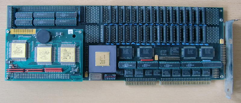
Most likely built & released 1988, this full-size ISA board features a Clipper C100 CPU(set), 4MB of ram (expandable to 8MB) and quite some glue-logic, mostly buffers, lots of GALs, some DP-RAM – and sad enough: no EPROM.
Having no EPROM means it was “booted” by the hosting PC and there’s no clue of how to feed this beast, i.e. what kind of protocol it is talking to the ISA bus.

A german article in the endless archives of “Computer Woche” (21.10.1988) mentions this:

[…]Für den SPEA-Panther, einem Aufrüstungsboard für PC, steht jetzt die CAD-Software Intergraph Microstation zur Verfügung. Besonderes Merkmal dieser Software ist, daß der Kern unter Unix läuft, die Anwenderschnittstelle jedoch eine DOS-Lösung beinhaltet. Microstation liest und schreibt DOS-Files. Auf Grund der Lösung “Unix under DOS” ist die SPEA-Version von Microstation voll kompatibel zu Workstations.” (Source)

Translated:

“[…]For the SPEA-Panther, a PC expansion card, Intergaph’s CAD-Software Microstation is available now. The particular feature of this software is that its core runs on UNIX while the user-interface is still hosted on DOS. Mircostation reads and writes DOS-Files. Because of the “Unix under DOS” solution the SPEA-version of Microstation is fully compatible to the workstation [version]”

So the Panther was probably running a full version of CLIX, Intergraph’s version of UNIX and the x86-Host was degraded to be the terminal… given the 1988 speed of PCs (Compaq just introduced the DeskPro 386 @ 16MHz), not the worst idea to have.
Well, if it wouldn’t to be the case that the Clipper architecture itself was dying a slow death over the next 2 years…and Autodesks AutoCAD was getting faster as 386/486’s were taking off…

That’s probably the reason why there’s next-to-none info about this card on the web… and print and newsgroups: Too expensive, too specialized, just a hand-full sold.

So just for the fun of it, here are some more detailed pictures of this “one of a kind”. The right half of the card has the ISA bus interface, four chips from Fujitsu marked MB622202 (my guess is it’s Dual Ported RAM), lots of 81C4256 DRAMs (32, so 4MB) and a mysterious gold-lid PGA Fujitsu chip marked C143C1C and 76460… could be anything. Ah, and a dip-switch… most likely for setting the I/O address or IRQ.

panther_right

The left side of the card is dominated by the CPU daughter board, obviously provided by Intergraph itself (featuring the companies logo) as I had seen this kind of board before. Above the CPU are even more PAL/GAL chip.
And again, the unknown C143C1C chip, now in its full glory. Next to the chip a 60MHz oscillator which lets me guess that the C100 runs at 30MHz… a bit below standard for C100s.

panther_left

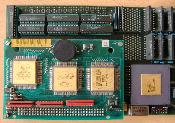
When buying the card my hope was that there might be more enlightening stuff below the CPU daughter-card. But as most times in life… there was nothing worthwhile 😉

panther_below_CPU

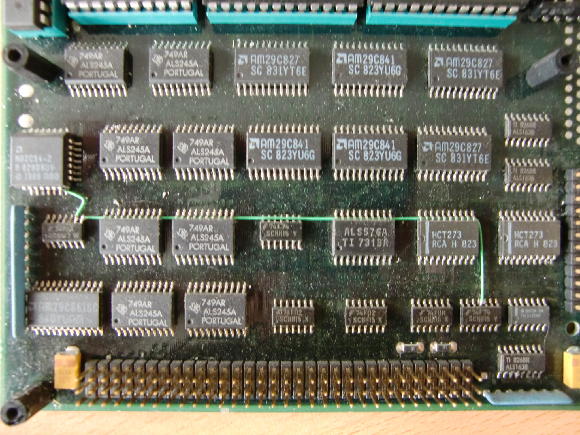
Just lots of TTL logic and buffers… the PLCC on the left is a N82C54… a CHMOS programmable interval timer… boring.

So to conclude this chapter, I guess I won’t make this card run again – ever. It’s just another example of how undecided the computing world was around 1988. There where more than one way to reach your target (speed) but most of them failed. Still I think it was much cooler than today.

Update 2016:

Found an interesting auction on ePay… this is the original Clipper card – which seems to be the “blueprint” for the Panther… SPEA just replaced the tons of discrete logic by some ASIC chips, which made room for RAM. On the  original cards that is placed on a separate daughter-card:
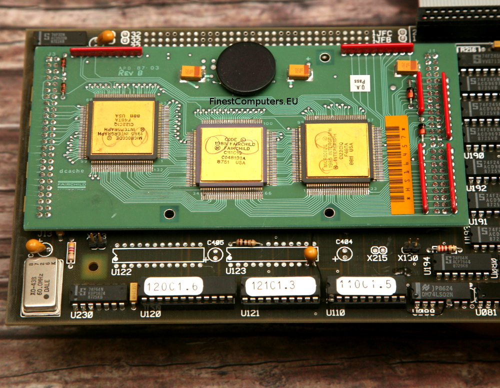
(Pictures courtesy of FinestComputers.eu)

Clipper_total_f

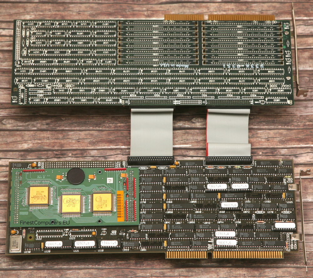
The CPU card back side and RAM card front:

Clipper_total_b

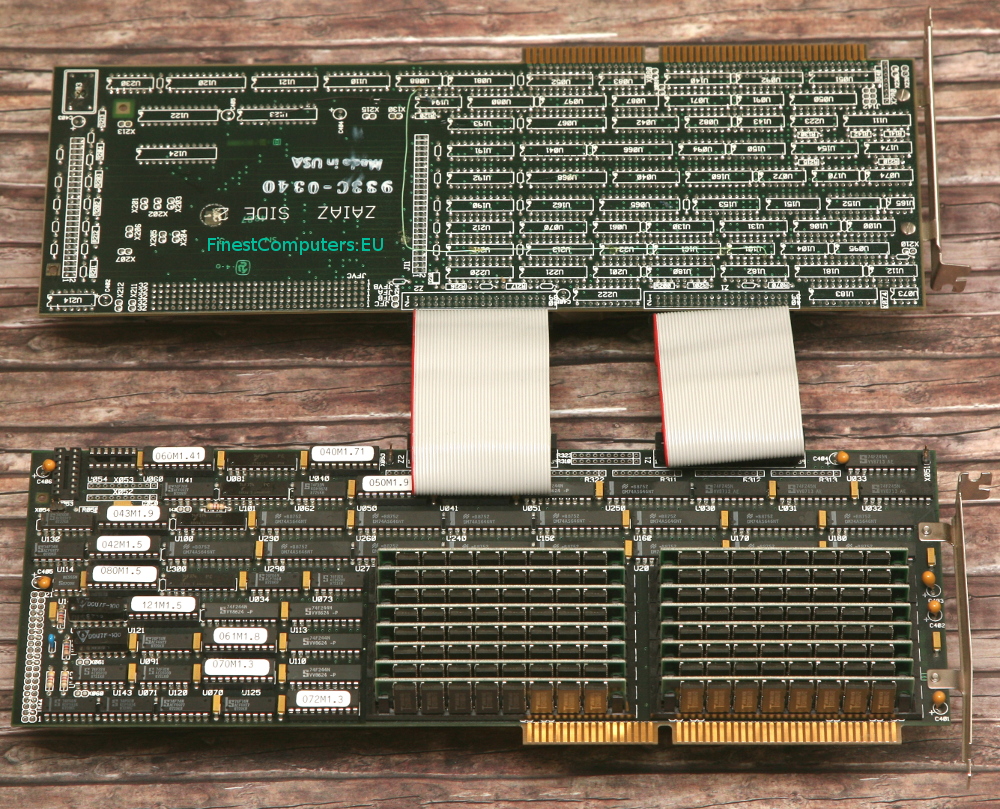
The CPU Module is the same as used by SPEA:

Clipper_detail

TIGA – The basic stuff

Welcome to the TIGA basics page! The fist post in my little TIGA chapter.
You probably came here because you just got (or plan to buy) a cool, shiny TIGA card and like put it to some use. Or you’ve read about it and found out, that the Web is pretty thin on that matter… Anyway, you came to the right place!

Let’s check some points fist…

Hardware

Well, if you have a card already, great, you’re set.

There were/are different versions around. The early cards used the first implementation of the graphics controller called TMS34010  which was clocked up to 60MHz (amazingly high!). For example TIs very own “TIGA Star”:

Later models used the advanced TMS34020 which started at 33MHz up to a max of 40 but had faster instruction cycle times, a faster memory interface and a twice as big instruction cache (512 bytes. Yes, bytes). Additionally the ‘020 supports the rare TM34082 floating point co-processor (actually even more than one) to speed up 3D calculation. I’m not aware of a Tool using that…

One of the first ‘020 cards was probably the Diamond from TI, which even features a socket for the FPU:

My weapon of choice is the mighty Miro TIGER:

Every TMS340 has its own RAM to run “programs” in. Depending on the model this starts at 1MB and can sometimes expanded up to 17MB. Better cards used SIMM to do this, but there were some models which used  proprietary RAM modules which are nearly impossible to come by these days.
Next the TMS340 needs VRAM, the memory holding the graphics itself. Again, depending on the model, this might vary from 1 to 4MB resulting in different max resolutions. IMHO just 1MB doesn’t do a TIGA card justice. That is just enough for 640×480 in 24bit…
Finally, as TIGA was not a standard CGA/EGA/VGA replacement, you’ll need some way of displaying the DOS text/graphics output. TIGA was always meant as an additional display mostly using a 2nd high-resolution screen, so TIGA cards either run in parallel to an existing VGA card or it also features a (mostly simple) VGA controller for this.
Very sophisticated cards like the above miroTIGER gave many options for this. It features a small VGA part (a Cirrus Logic CL-GD540 and 256K of DRAM) to make a 2nd card unnecessary or could disable that to use a 2nd card of your choice for a two-screen-solution or offered to loop-though the signal of an existing VGA card and automatically switch between them for a single-screen-setup.

Recommendation

So if you consider buying a TIGA card, go for a TMS34020 with SIMM sockets. It should have at least 1MB RAM and 2MB of VRAM. A SPEA Graphiti FGA is a good example for this minimum config.
While DRAM isn’t that important, the more VRAM you have, the better. Having a VGA controller on board might be desirable if you’re tight on slots – but to my knowledge the best VGA controller ever used on-board  was an ET4000. So it’s more or less a matter of taste.

Software

Actually this is the more important point on your list. While yes, TIGA is a standard, it contains certain proprietary parts, called the CD, GM and EXTPRIMS you’ll need to get your card going. The reason for this is the driver which is more a layer model looking like this (listed bottom-up):

Application using TIGA (e.g. AutoCAD)
application specific extensions (also *.ALM/*.RLM file)
extended primitives (EXTPRIMS.RLM/*.ALM)
Graphics Manager (e.g. tigagm.out)
Communication Driver (tigacd.exe)


The 3 yellow(ish) levels are card-dependent, so without them, you’re lost and your shiny TIGA card just makes a nice paperweight.
The lowest level is the Communications Driver, or CD for short, is 100% hardware dependent –  It is always supplied by the cards manufacturer and, well, handles the low-level communication and resides in the PC (upper-)memory.
Above that sits the Graphics Manager (GM)- this is the “real thing™”, the core or kernel of TIGA – which is the firsts thing being loaded into the cards own DRAM.
On top of the Graphics Manager sits another layer belonging to the package provided by the card manufacturer and loaded into the cards RAM, the Extended Primitives Library called EXTPRIMS.RLM in 99% of all cases. This contains all the drawing routines for primitives e.g. boxes, circles but also printing text etc. The file extension ‘RLM’ stands for relocatable load modules while ALM means absolute load modules. RLM’s are loaded and linked at run time, ALM’s are linked in advance for a fixed configuration and later at run time just loaded onto the TIGA card.

Here’s another illustration to show the layer model separated by memory regions:

With these 3 layers loaded, your TIGA card is ready to rock and awaiting commands from your application. Let’s take AutoCAD as an example – it’s probably the best example anyway as TIGA was mainly used for CAD.
It will not only load the TIGA driver but probably also some extensions provided by your cards manufacturer. So for example the miroTIGER came with a 3D-Viewer called “MulitVIEW”, ELSA provided a tool called ELSAVIEW with their Gemini cards etc.. All those tools loaded some extra code into the cards RAM (that’s the light blue layer).
All the extension tools I saw up to now didn’t require more than 200KB RAM. The TIGA core itself is at ~100KB, so for most basic stuff 1MB might suffice at first – but of course some of those tools need extra RAM for holding data so my assumption is that 2MB are a good bet to start with.

Caveats

All that said, be aware that were two main versions of the TIGA kernel – V1.x and V2.x which have slight differences in programming. Again, it depends on the model of your card which TIGA version is supported. As far as I know, V2.x (2.2 being the latest) requires a TMS34020.
ALM’s were a unique feature of TIGA V1.1 and should no longer be used with TIGA V2.0. Generally, V1.x programs do not run (properly) on a V2.x CD/GM combo.

Setup

First, most likely there might be something to setup on your card. DIP switches for example or jumpers. At least you need to know/set the base-IO address of your card. Lucky are those who have a manual 😉
Next, as this is DOS-land, there are some things to set-up in your config files. As usual with DOS, you have to set an environment variable in your AUTOEXEC.BAT:

SET TIGA=-mC:\TIGA -lC:\TIGA -i0x60
PATH=%PATH%;C:\TIGA

This defines the path(es) to your TIGA modules and libraries as well as the base-IO address, at which your card is communicating. This has to be adjusted to your hardware setting.
Also the base-path to your TIGA files needs to be in the system path.

Then you load your CD and (optionally) GM:

lh C:\TIGA\TIGACD.EXE
lhC:\TIGA\TIGALNK.EXE -LX

The 1st line is clear – if your config allows, you can load the CD into upper-memory. With the 2nd line you can pre-load the GM into the cards RAM and the -LX parameter makes sure it eXecutes right after that. This step is optional, as well programmed TIGA programs check for the GM and if it’s not loaded, they’ll take care of that.

That’s about it. Yay, your TIGA system is up and running 😀 and you’re ready for some action.

The next post shows how to program your TIGA card and do some graphics…

ARM eval boards and Helios

     “Every end implies a beginning.”

This post started out as a special Helios article, but given the rarity and historical importance of the used hardware, it’s now somewhere between the worlds of OS and Hardware – and the combination marks the end of an operating system and the launch of an incredibly successful processor family.

Helios is most likely already one of the loneliest OSes on the planet… I estimate about 10-20 active Helios installations of the Transputer version currently running. But the Helios ARM version supposed to run on my VLSI ARM eval boards is probably the only one on planet Earth.

Quick history digression

Talking about lonely… The  eval boards we’re discussing here, the VY86PID family, was what you could buy from VLSI. VLSI  founded  ARM Ltd. together with Acorn and Apple.
So you’re actually looking at the birthplace of your mobile phones processor right now. This is, where it all started!

When you’ve planned to build a computer based on VLSIs range of ARM CPUs back in the days – most notable the ARM6xx, 7xx and ARM7500 series – you got a VY86PID board . And because not many did – mind the Acorn RiscPC and Apple Newton – those boards are rare as hens teeth today. Googling for it will most likely bring you back here 😉
There’s just one good, original source of information left: The page of Art Sobel himself, Hardware Applications Manager for Embedded products at VLSI Technology, father of the boards discussed here.

Last question: “Why VY86PID? That sounds Intel’ish, like the x86 family.”
Well, VLSIs official name for their ARM IC range always started with VL or VY86… so  for example the fist mass-produced CPU, the ARM2, was officially called VL86C010. It’s memory controller was VL86C110 and they used  VY86C610 for the ARM610.  Only with the introduction of their last ARM CPU, they changed it and called the ARM7500 VY27073B

Hardware

But now, let’s have a look at the eval boards first…

VY86PID 2

This is the earliest implementation of a PID I ever saw and own. Its components are:

  • ARM600 CPU at 30MHz – soldered onto the board
  • 4 SIMM slots for 1-16MB RAM
  • MEMC3 memory controller on a 12MHz bus
  • ‘INTWT’ INTerrupt (With Timer) controller (Maybe a VL86C410 derivative)
  • VL16C552 Serial/Parallel controller serving an on-board connector each
  • 128KB-1MB ROM (jumpers used for setting the size)
  • one ISA compatible expansion slot
  • 4 status LEDs, Reset- and Panic-buttons
  • an empty PLCC68 socket for the FPA10 FPU from GECPlessey
  • edge-connector to connect a ‘logic analyzer probe board’

It’s worth mentioning that both controllers, the MEMC as well as the INTWT were implemented in QuickLogic ‘pASIC’ QL8X12B 1st generation FPGA. That’s about 1000 gate arrays – tiny in today’s measures. That’s interesting as the MEMC was available as commercial ASIC already – but it that could only support 4MB explaining the appended version number “3”.
Also, take note that the PID2 uses an ARM600, not the later widely used 610 (RiscPC, Newton 1xx series). The 600 features support for a floating point co-processor, ARM Ltd. usually used the term floating point accelerator – this was only supported with the ARM600 & 700 and later integrated in the ARM7500FE.

VY86PID3

This is the PID3, sometimes also written PID III – this time it’s processor-independent for ARM610, 710, and 810 CPUs, featuring a connector for a CPU module which is 100% compatible to the ones used in the Acorn RiscPC.
Most parts are similar to the previous PID – even the FPGAs – so these are the notable differences:

  • No CPU on-board – instead it offers a slot
  • 10BaseT Ethernet port (SMC 91C94) with 4 status LEDs
  • the empty PLCC socket was removed

Luckily I got an extensive manual with it, even containing all the schematics. Boy, those were the days, when manuals were real manuals!

vy86pid3b

The PID3 with (dis)connected CPU board (it’s an ARM710 card from Acorn RiscPC)

vy86pid3a

So far for the hardware. Both run a rudimentary monitor program from ROM – so let’s have a look into that…

Software

Out of the box the PIDs run a monitor program called “DEMON”, short for DEbug MONitor.
As with most single board computers (eg. Motorola VME boards) those monitors are more or less command-line BIOSes with some debugging features (read/write memory & registers) and are mainly used to load binaries and start them.


The toolchain which came with the eval boards is available here. It even includes a (cross)C-compiler and libs in source!

Helios (so far…)

This was the reason why I bought the boards – getting Helios run on ARM. The original Helios sources which I’m hosting on github also came with a kernel for ARM, specifically the Acorn Archimedes and, well, the PID2…

Historical side note: Why Helios on ARM?

Well,  at the time this port was done it became obvious that the INMOS Transputer wasn’t developing as fast as other CPU families did and so Perihelion, like other INMOS customers,  turned towards alternative architectures.
Also they looked for more profitable market: “The emphasis by this time was to make an embedded real-time system rather than an interactive Unix clone” [Nick Garnett, designer of Helios] Set-top boxes come to my mind… and later SGS-Thomson was quite successful in that area with their Transputer based ST20 family.

There are 2 supposed ways on getting Helios onto a PID – both using an RS232 connection:

  1. load the kernel through the Helios server (that’s the DOS/Unix terminal tool) which then talks to the DEMON or
  2. Have Helios burned into EPROMs instead of DEMON.

I wasn’t able to get the EPROMs work (binary image here) – or more precisely, connect to the system. It didn’t accept connections from the server, even the readme says so. The LEDs a showing a heartbeat pattern, so I assume the kernel is running – but without a shell connection I can’t tell more.

The alternative way by uploading through the server looked more promising… I got it stable at 38400 baud and using the debug flag (ctrl-shift-c) I could see the bytes flying upwards…

…but then it looses the connection, misses an ACK and then  fails to send the system config.  The server – while successfully initialized – then sits and waits forever  😥

To be continued…

TIGA programming

After we talked about the basics of the TIGA standard in the previous post, we’re now  trying to do some TIGA programming… (mind the absence of the word “useful”  😉 )

I can’t stress this enough: Compared to even the earliest 3D accelerators TIGA wasn’t fast. Actually it’s not meant to be a 3D accelerator at all, it’s a 2D accelerator which tried to cope with the slow ISA bus speed. With the arrival of VL-bus and then PCI, TIGA hadn’t had a chance – even with a TMS34082 FPU it reached a max of  160,000 polygons/sec and 25,000 shaded polygons/sec – and there’s no real support for textures. Fun fact: An original PlayStation (1, that is) did 180,000 textured and lighted polygons/sec…
Ah, and before you ask: No, there was no native Linux X11 support ever. There were two X11 servers: MetroLink offered a “stub” which translated X-call on the host to TIGA which ran on the card. And there was a DOS(!) X11 server from AGE Logic. That one ran solely inside the cards RAM, ignored TIGA completely and its speed was comparable to a Sparc 1 or Personal Iris  😕 The upside was, that was also the case on a slow i386/25 which was still usable running several tasks. So a lot of work was offloaded to the TMS340… OTOH you could invest that money in a i486 and a simple ET4000 to get the same responsiveness and got more CPU-Ooomp on top.

Demos

Anyhow, to have a quick start in TIGA programming, let’s do some demos… but before we start, make sure you can tick every point on this list:

  • You’ll need a running DOS (>= v3.2) system
  • Obviously a TIGA graphics card in an (E)ISA slot – VMs won’t take you far here.
  • A successfully loaded CD and GM (what’s that? Read the 1st TIGA post over here!)
  • A decent C compiler – I use Borland C (Turbo C v2 is fine, too) for that
  • The API documentation PDF from TI (aka “Interface Users Guide”)

…and the libraries. Those came in the so-called DDK (Drive Development Kit, download it here), which was meant to develop drivers on the DOS side of things but can also be used to write some code making use of the insane TMS340 powers 😉
This DDK contains some (thin) documentation of how to set-up your compiler and the important libraries as well as the include files.
Just unzip the archive to some place you can remember – I used C:\TIGA on my box.

Setup

There are some things to be done in the Borland/Turbo C IDE before you can compile code with the DDK.

1. Add the directory path-name of where the TIGA include files are located in the Options/Directory menu. e.g.:

Include directories: C:\TURBOC\INCLUDE; C:\TIGA\INCLUDE

2. Add the directory path-name of where the TIGA Application Interface Library files are located in the Options/Directory menu, e.g.:

Library directories: C:\TURBOC\LIB; C:\TIGA\LIBS

3. Specify the TIGA Application Interface library in the Project-Make
file. Simply add a line “AI.LIB” into your Project-Make file. No
directory needs to be specified since the path name was added to the Options/Directory menu as described above.

If you prefer to use the command-line it’s most convenient to add the paths in the call. E.g. building demo.c would result in this call:

tcc -Ic:\tiga\include -Lc:\tiga\libs -ms demo.c ai.lib

The code

Ok, so your dev-system is all set. The TI documentation is pretty good and, well, the only one you can still find these days. So make sure you gave it at least a quick glance-through. By the way, we’re only doing TIGA v2.x stuff… the DDK is not v1.0 compatible.

Have a look at Chapter 3.4. (PDF page 45), it gives a good intro how a basic TIGA application setup looks like. Basically that’s:

  • First check for a Communication Driver (CD) and then open a connection to it
  • Do your thing
  • Properly close the CD
  • exit(0);

The opening and closing of the CD are wrapped into the init_tiga() and term_tiga() functions, so I’ll use those in my samples, too. So here’s a rudimentary example without the aiding functions and #includes needed. It’s drawing a blue, solid filled rectangle, half the size of the screen, centered in the screen:

init_tiga(1);                       /* initialize TIGA*/

get_config(&config);                /* Get info on current mode */
width = config.mode.disp_hres >> 1; /* Width 1/2 screen width */
height = config.mode.disp_vres >> 1; /* Height 1/2 screen height */
xleft = width >> 1;                  /* Center rect in middle */
ytop = height >> 1;                 /* of screen */
set_fcolor(BLUE);                   /* Set foreground color */
fill_rect(width,height,xleft,ytop); /* Fill the rectangle */

term_tiga();                        /* Properly terminate TIGA */

Pretty straightforward, huh?

So without further ado, just do something more impressive: Animation!
Well, don’t wet your pants, it’s just a spinning wire-frame cube, but hey! That was quite something back in 1990 😉 It also shows the usage of extended primitives, i.e. drawing functions which might needed to be loaded onto your TIGA board first (depending on model)
The code is a bit longer, so here’s the ZIP archive, which includes a TurboC project file for your convenience, too.

As soon as I figured out, how to do decent screenshots from the TIGA frambuffer, I’ll post a piccy here.

BGI Driver

Sounds like a strange thing, but might be handy at times if you want to port your brilliant BGI application fast. And well, that’s what the BGI was meant for, right?
The driver was written in 1990 by ‘TSS Rolf Bartz’ and is most likely abandonware…

So this BGI ‘driver’ or better called a wrapper will translate BGI calls into TIGA… of course there are some limitations in speed.
Also out-of-the-box all functions use the BGI maximum of 256 colors but up to the max. resolution your TIGA card provides (well,16384×16384 is the limit ;-)).

That said, there’s a very good readme included (read it!) which not only explains how to use the driver but also tells you more about the enhancements Rolf ingeniously added:

  • There are calls for circles/ellipsoids to bypass the emulation of some calls and use genuine TIGA calls – that should speed up things quite well.
  • FillPoly uses the native TIGA call if there’s enough RAM for a workspace
  • He patched SetWriteMode so that you can use the full 24-bit TIGA color palette.

Again: This is a work-around and should not used for new projects.
If you successfully coded some demos, please let me know!

An odd end…

Finally, I’d like to share some heavy stuff: The Digital Micronics Vivid 24.

Yes, it’s an AMIGA Zorro III card, but at heart it’s TIGA… to the max! TMS34020 40MHz, two (2!) 34082 FPUs can be added, max. 8MB RAM and 16MB(!) VRAM… that’s some serious TI-o-rama. In 1992 this beast costs nearly 3000US$   😯