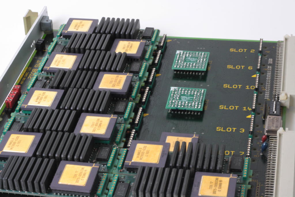
The IMSB012 is my favorite TRAM carrier board. Room for max. 16 (size-1) TRAMs and plenty of external connectors. The perfect platform to build a successor of the ‘Tower of Power’.
Like with all TRAM carriers having more than 8 slots, it was a good decision to put at least one C004 link-switch onto the board.
While that’s generally a good feature, you (and me) might not need the option to reconfigure your Transputer network several times a week… And if you’re completely sure how you like your network it would be better to set if once and for all without the signal delay penalty you have to pay using one or even two C004s.
So in my case, I’m perfectly fine with the 4×4 matrix mentioned in the B012 manual (and also used as an example in my C004 post). So instead of using the clumsy MMS tool and having an extra link used into the T212, I planned tp remove the T212 and the two C004s and replace them with two dummies. Pretty much the same way like Parsytec did it with their x’plorer.
First I had to chew myself through the B012 schematic to understand the connection of each TRAM slot into the C004s. After that it was time for some intense cable plugging:
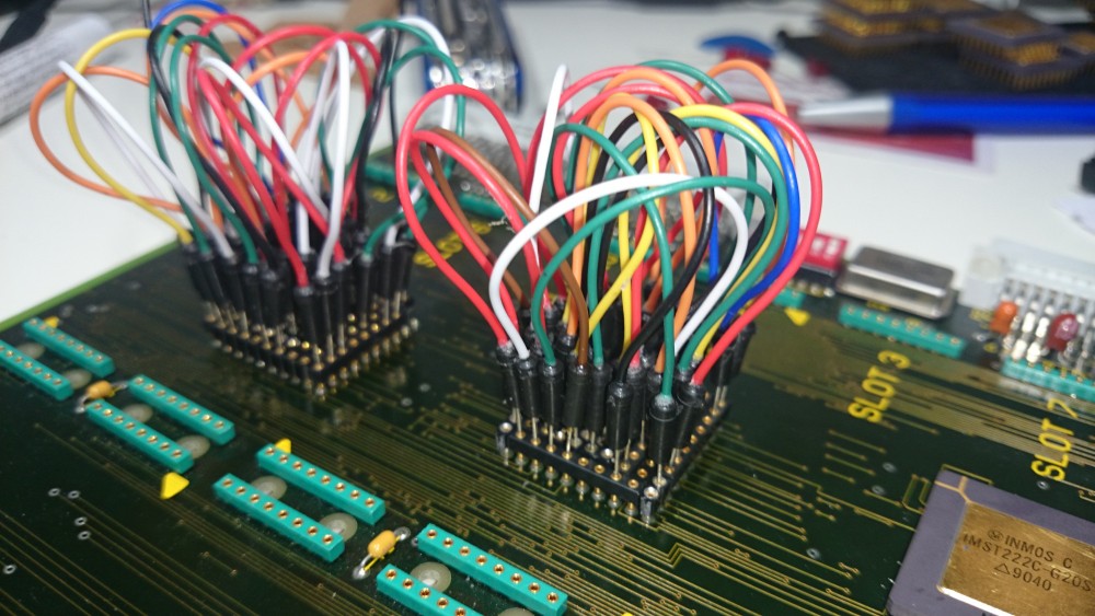
If you plan to do so, please be aware that the socket holes are too thin for a normal (0.63mm?) jumper cable. You might ruin your socket if you use force to plug them in!
I created a interpose socket by using single row pin header sockets which itself had thin enough pins to fit into the original B012 socket.
After some corrections, the buzzing-through of all 16 slots went fine and the schematics went to the PCB house (I have some PCBs left, ask for a quote if you need some).
And this is how the C004 replacement PCBs look when completed:
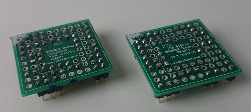
Again, to solder in the pins, you’ll need really thin ones. Thinner than 0.5mm that is. Also, you don’t need to populate all 84 pins, I only use 51 per dummy (bridging some gaps).
Additionally, I strongly advise to isolate each dummy’s top with some kind of tape to avoid (electrical) contact to the TRAM placed above it. This is how they look seated on the B012 underneath slot 6 and 14 – the T212 under slot 7 not yet removed: