
I bought this Atari 2080STF in 2003 and stored it as-is in my collection. The ST being my first 16bit machine I thought it could be a good point in time to un-dust and resurrect it 16 years later.
Atari 2080STF… 2080?? Yes, that’s true. There are different stories out there about their prototype/fake status.
As far as I see, there are two 2080STF versions out there:
- The “Yugoslavian Version”
- My Prototype
The Yugoslavian 2080STF is a pretty simple re-batching of a 1040ST which was upped to 2MB RAM and sold by a company called Mladinska Knjiga.
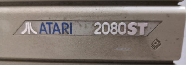
My 2080STF is different. In contrast to the Yugoslavian it features a proper, 3d embossed label, not some flat DIY thing.
Instead of some serial# printing looking like made with a children-stamping kit it says this:
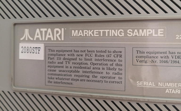
Marketting? Well… somebody’s been in a hurry or not native to English. Anyhow, the label shows the same quality as those used with Ataris produced in greater numbers. That said, there’s no serial number and the model ist just a paper-sticker.
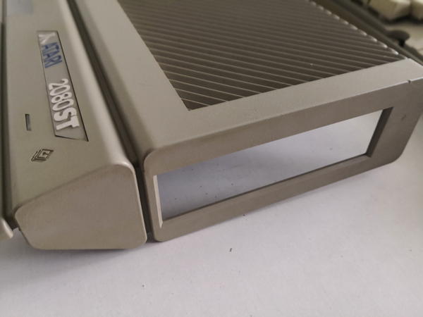
Next unique thing is the floppy cut-out on the right side. It’s the same square one like on a Falcon, but the plastics are in the proper ST grey. Mhhhh….
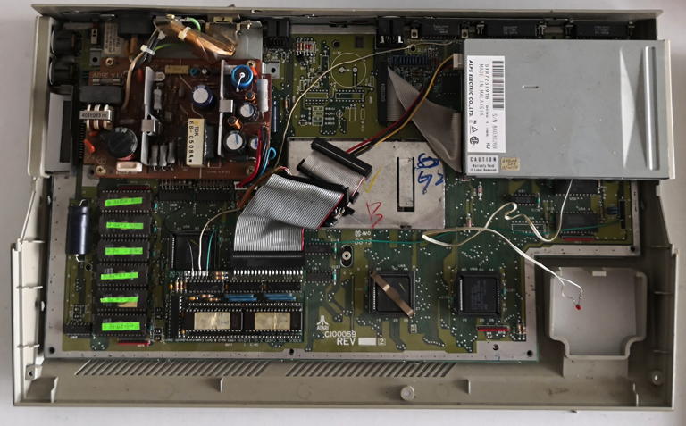
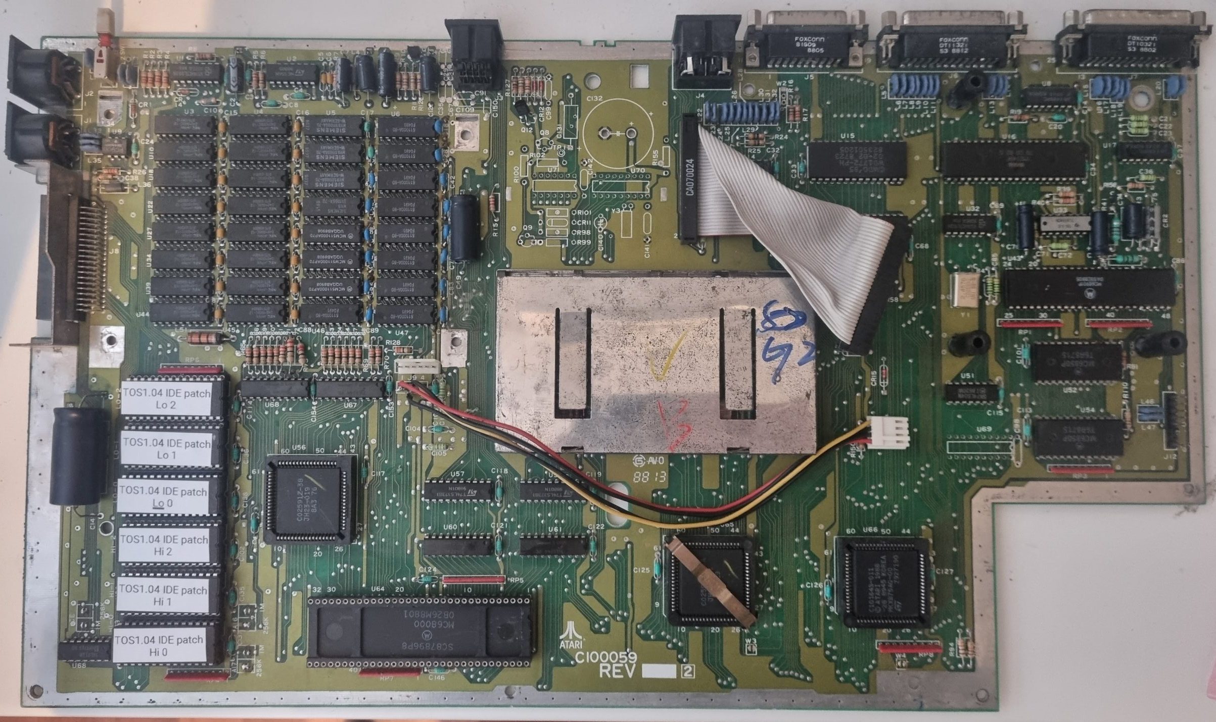
Finally the mainboard: Yes, it’s very 1040STFM without the M(odulator) part. But then it features a yet undocumented issue number of C100059, production week 8813. And mind the installed Blitter at the lower right.
So what do we got here? Not having any matching-numbers system like in the vintage car world, we can only guess…
It might be a real “Marketing Sample” made for a planned pimp-up of the 1040 family. On the other hand it also can be a nicely composed Frankenstein system made of parts e.g. being sold at Ataris sell-out in 1995.
Given the sum of the unique parts being used, I opt for the “real marketing sample”, probably being put together using available parts and meant for checking out, if there’s a demand/market for such model(s)… and history taught us that there wasn’t.
Anyhow, I pulled out the crap which had been “installed” over the previous years…
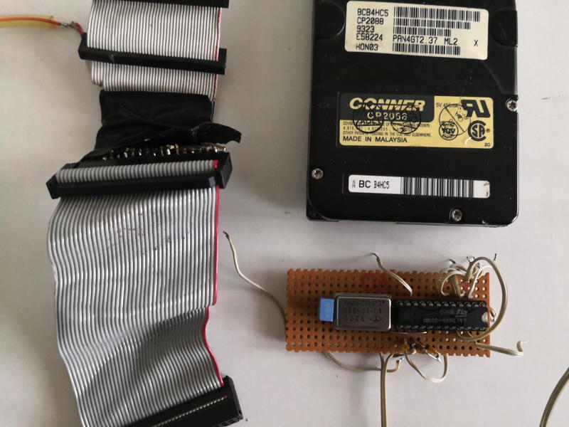
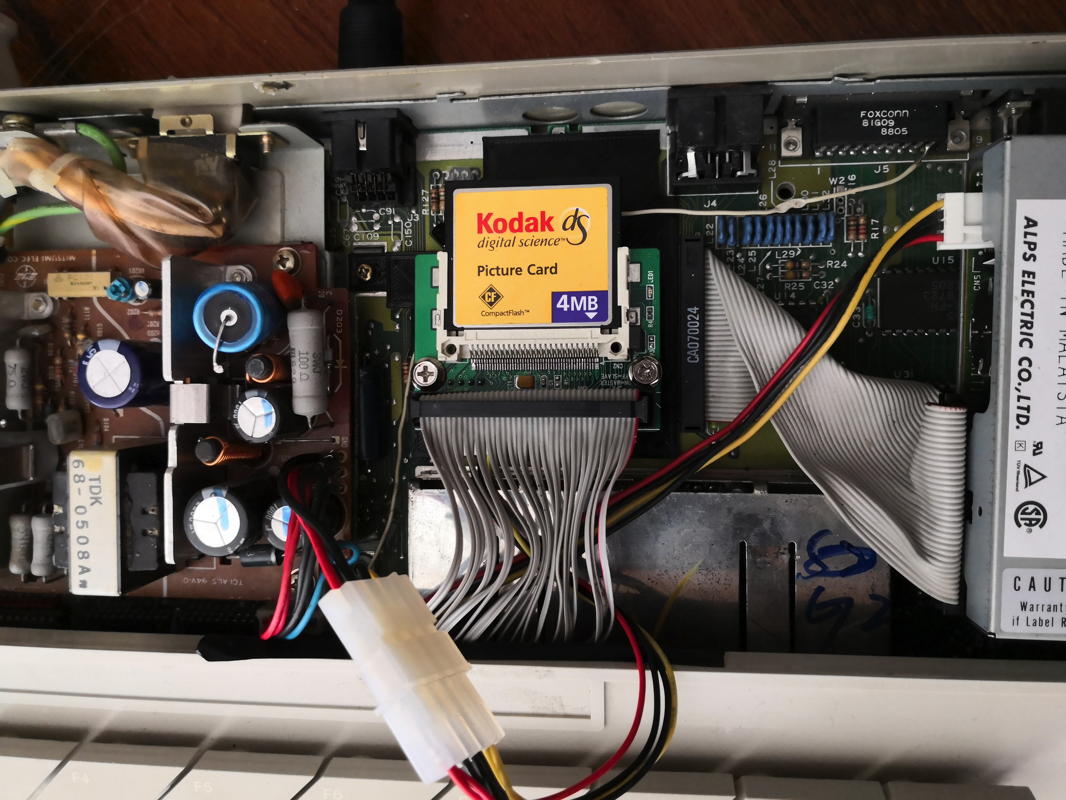
So the noisy 2.5″ 80MB harddrive got replaced by a CF-Card which nicely fits where the modulator would be, if this would be a STFM.
Additionally I 3D-printed a mounting thing for it which you can download here.
Finally, the build-in Hard & Software TOS-Card II 2.06 (that’s a long product name!) got fixed so it actually can switch between the on-board TOS and the 2.06 sitting on the card.
When everything’s done, it looks nice and tidy down there:
So I think I’m all set for some pure 8MHz 68000 fun… oh boy, did I love those days.
Restauration
In 2026 (23 years after getting it!) I decided to give this rare ATARI more love… which it really deserves – shame on me!
So I stripped it to clean things and (again) freed it from all unnecessary things.
Here’s the bare board (Rev. C100059). I removed the TOS2.06 & IDE interface and the MAG!X ROMs, which I replaced by “contemporary” TOS 1.04 ROMs.
Like some of you mentioned, this prototype board has something very special, no all-in-one ATARI ever had:
In the top-middle section of the board, where you’ll normally find the TV-modulator in an 1040STFM is an unpopulated space with a very suspicious marking:
So even it’s a rare model, I thought: “Would it work? Was it left empty intentionally or they just hadn’t the time left populating it?”
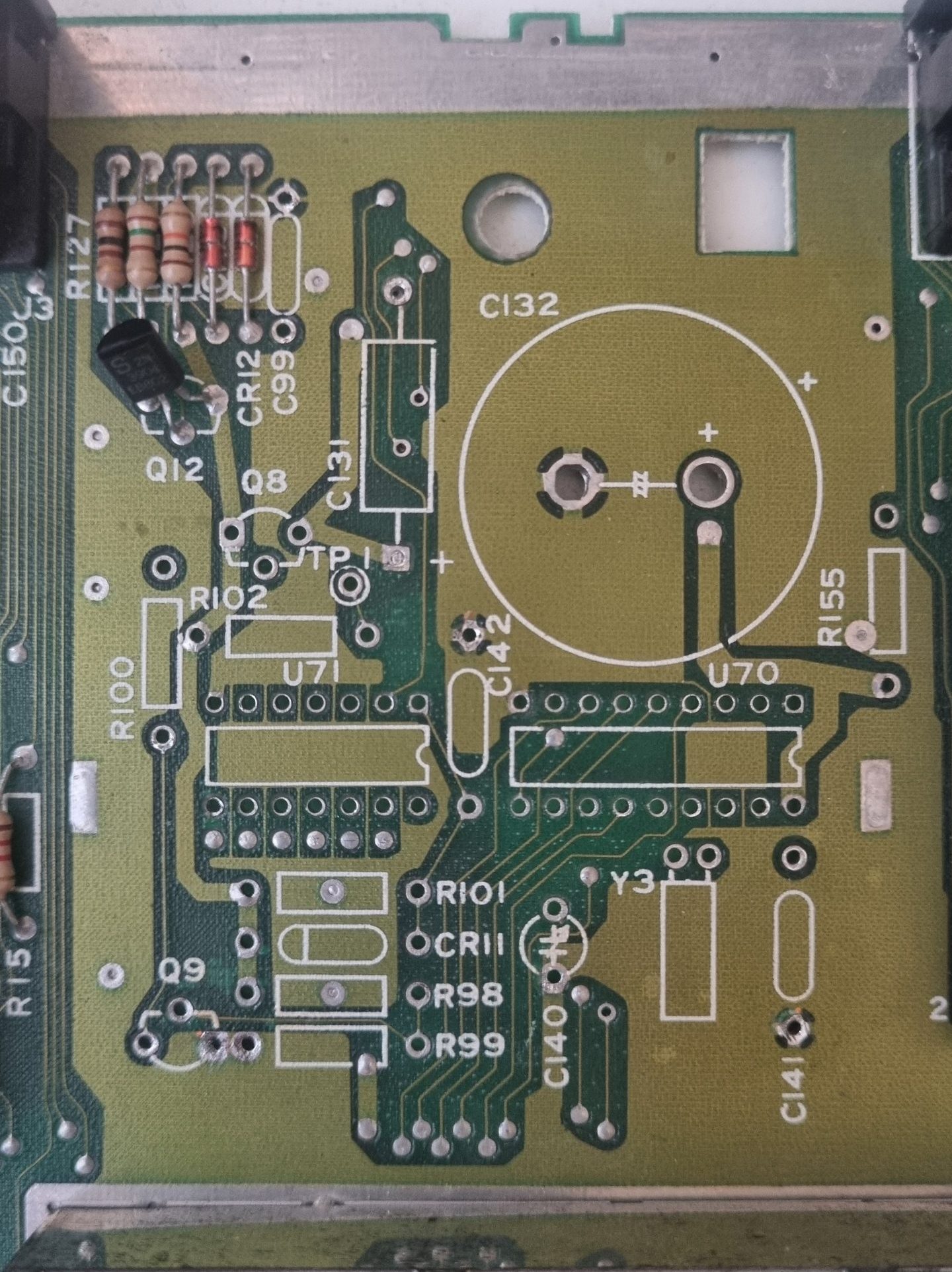
So I started to check the empty spots and silk-screen printings to the original Mega-ST schematic. All major parts are there… but where’s the RTC-PAL?
Ah, there it is. In the bottom left corner of the board, next to the two ACIAs where is also sits in a Mega-ST.
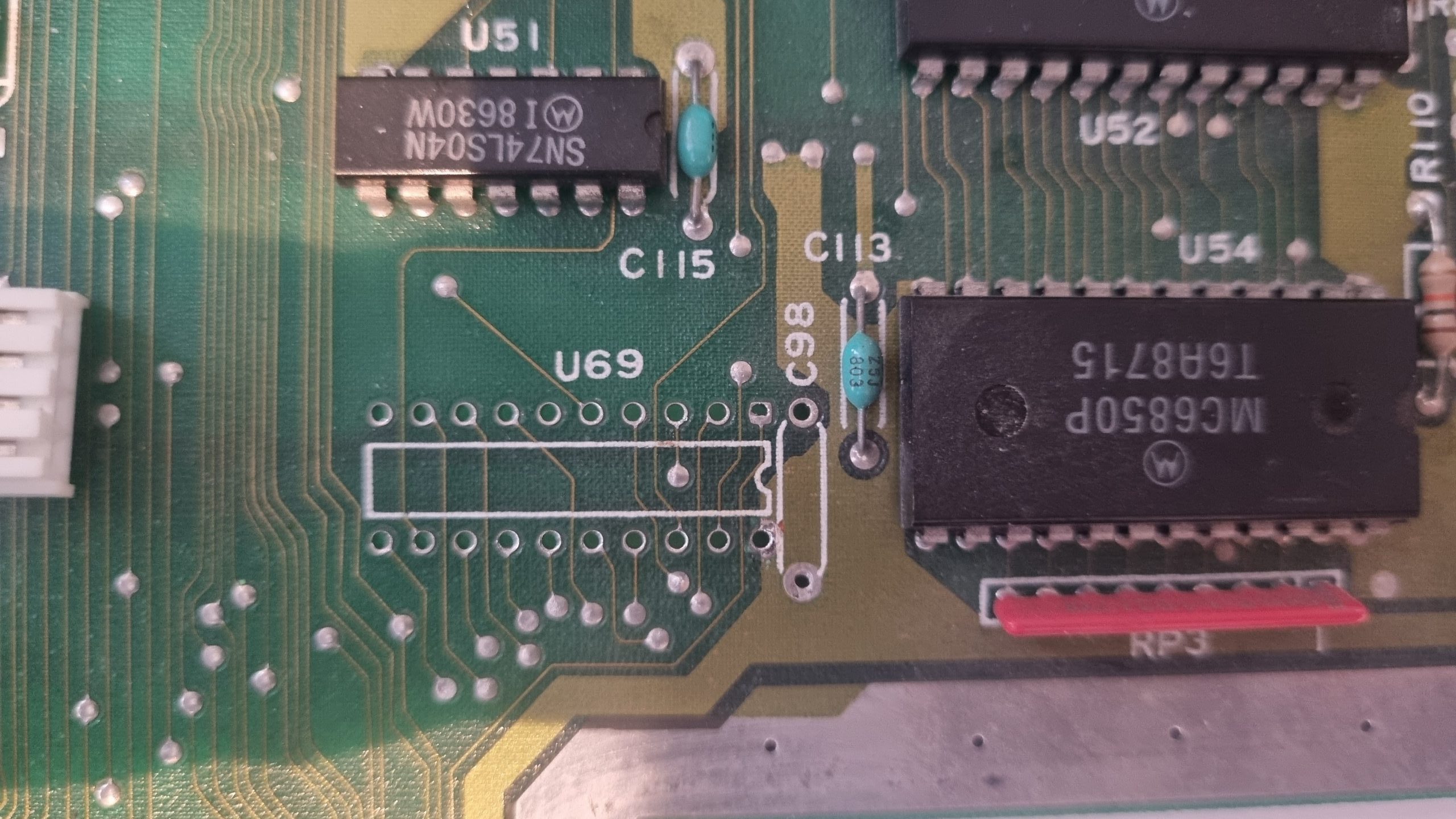
Here’s the mapping… the part-markings are different of course.
ATARI would not be ATARI if there wasn’t a mistake in the on-board markings.
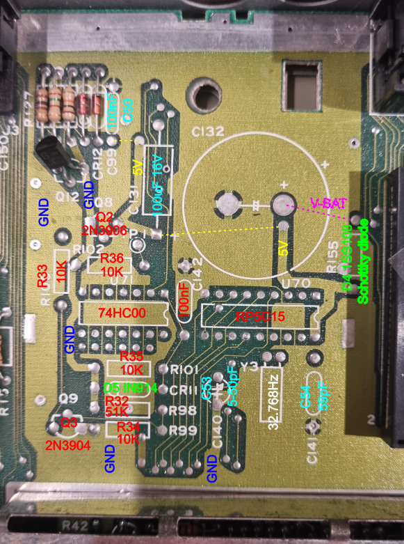
“R155” is not a resistor but a Schottky diode. But everything else was more or less 1:1 Mega-ST design.
With the part name I added the marking of the original Mega-ST schematic.
So in went the parts. The almighty internet gave me a JED file fpr the RTC-PAL and reading its specs, it was a good bet that the 32.768Hz I use needs about 22pF caps.
The coin-battery holder was meant for a bigger cell with an unusual pinout – so I mended a CR2032 to fit. All done, it looks like this:
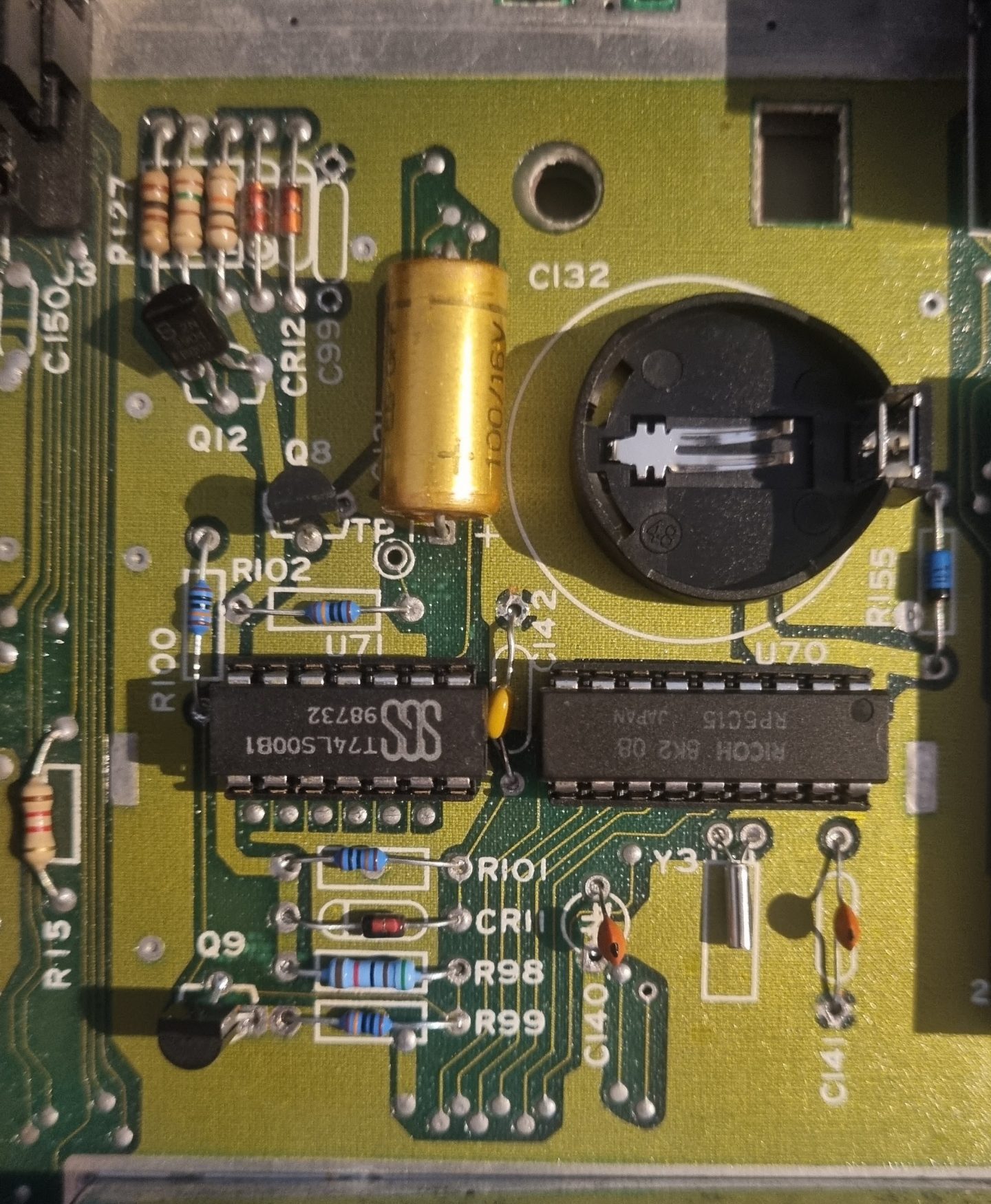
And the GAL (Which is a “more modern” 16V8H PALCE here):
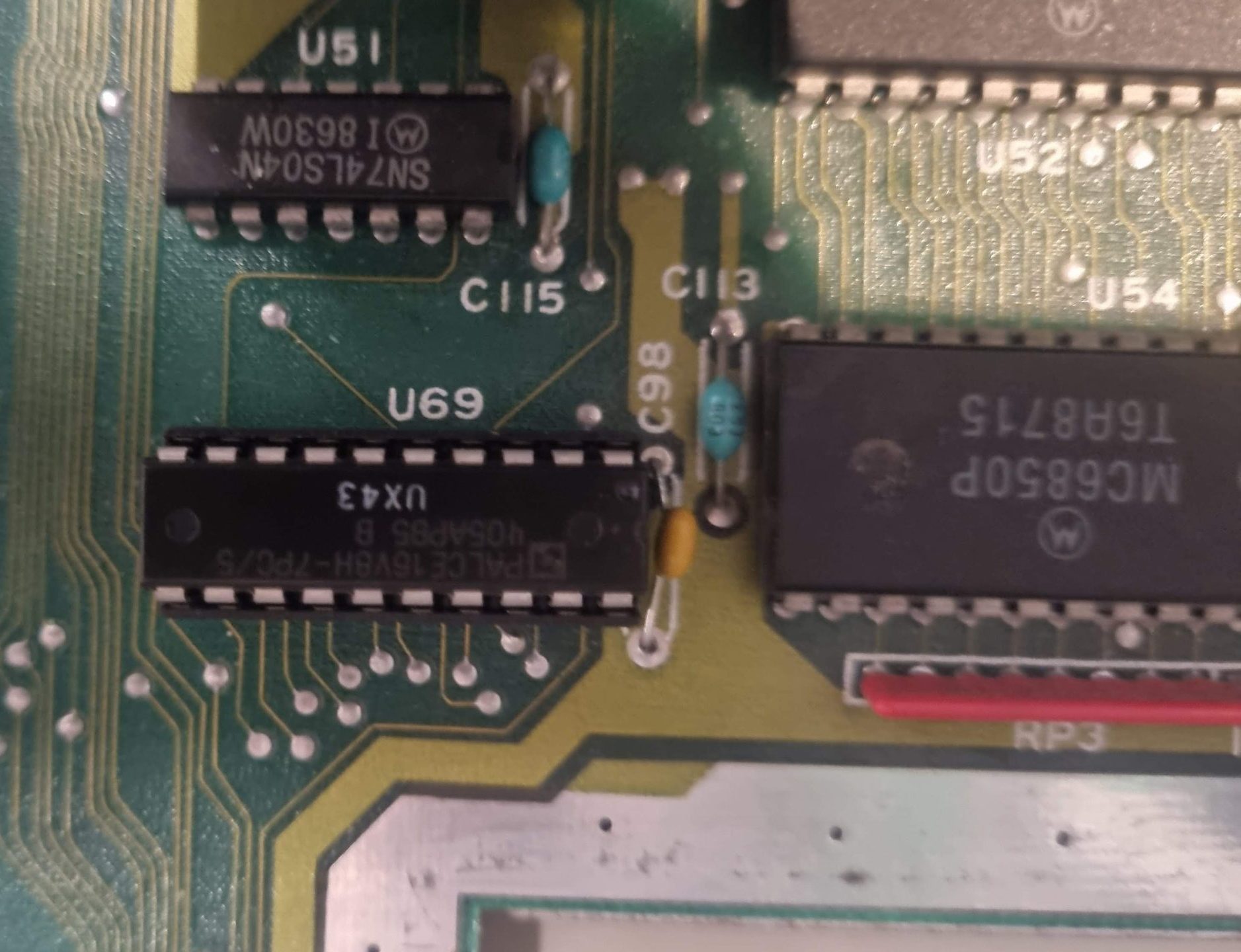
After this – lo and behold – this prototype is even more unique.
Actually, it’s like a Mega-ST4 in a 1040ST case – RTC and Blitter included.
Next up: Clean the case and keyboard real good. But that’s boring, so no documentation here 😉
Waaaait, so it was supposed to be equipped with regular 1.44MB FDD? Or is it just coincidence and it has stanard WD1772 floppy cotroller?
I simply don’t know. Actually, you never know anything with these prototypes. Maybe they just used what was there… or there was a bigger plan. Without written prove all we can do is guessing.
Interesting is also the board space where in “normal” 1040STFM the modulator (or in 1040STF only the composite sync transistor) circuit would be found. Here, at closer look, there is no typical FBAS/Composite to RF footprint of components. The silk print and THT drills rather looks like room for:
– a coin cell battery holder
– the GAL (PALCE) with address decode function
– the real time clock (RTC)
This design would be known from the MegaST series and had also not found its way into the 1040STE design (although the address decoder and chip select is present in schematics and STE glue/mmu combo)
Yeah, that came to my attention just recently, too. I’m thinking about populating that. Most likely it’s a 1:1 schematic like the MegaST, so the GAL content is probably the same, too.